A high bed temperature circulating fluidized bed boiler with steam parameters of 700°C and above
A circulating fluidized bed and steam parameter technology, applied in steam boilers, fluidized bed combustion equipment, steam generation, etc., can solve the problems of difficult to achieve and balance the efficiency of circulating fluidized bed boiler units, so as to ensure long-term high efficiency operation, improve power generation efficiency, and improve the effect of heat transfer intensity in the furnace
- Summary
- Abstract
- Description
- Claims
- Application Information
AI Technical Summary
Problems solved by technology
Method used
Image
Examples
Embodiment 1
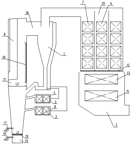
[0025] Such as figure 1As shown, this embodiment is a high bed temperature circulating fluidized bed boiler with steam parameters of 700°C and above, including an air chamber 14, a single furnace 11, a single air distribution plate 15 and several air caps (not shown). Air distribution device, primary air system with fan 16 and air duct, secondary air system with fan 17 and air duct, horizontal flue 18, two cyclone separators 1, two external heat exchangers 2, The tail flue 3 and the cyclone separator 1 are connected to the horizontal flue 18, the tail flue 3 and the lower part of the furnace 11, and the two ends of the two external heat exchangers 2 are respectively connected to the respective cyclone separator 1 and the lower part of the furnace 11 , the surroundings of the furnace 11 and the furnace roof are composed of water-cooled walls 19 with upper and lower headers, and the shrinkage ratio (that is, L1 / L2 in the figure) of the lower part of the furnace 11 along the dept...
Embodiment 2
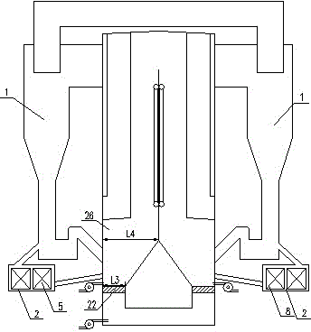
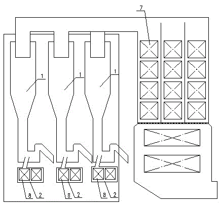
[0032] Such as figure 2 , image 3 Shown, this embodiment is compared with embodiment one, and its difference is only: its hearth 26 is single furnace hearth double air distribution plate structure, and the bottom is provided with two air distribution plates 22, and several air caps are respectively provided on two air distribution plates 22 (not shown), the shrinkage ratio of the lower part of the furnace 26 along the depth direction (that is, L3 / L4 in the figure) is 0.22, and three cyclone separators 1 and three external heat exchangers 2 are respectively arranged on both sides of the furnace 26 Among them, three external heat exchangers 2 are provided with medium-temperature superheaters 5, and the other three external heat exchangers 2 are provided with high-temperature reheaters 8, and the inner diameter of the tubes used in the low-temperature reheaters 7 is 46 mm. The internal diameter of the pipe used in the high temperature reheater 8 is 48mm.
[0033] The working ...
Embodiment 3
[0035] Such as Figure 4 Shown, this embodiment is compared with embodiment two, and its difference is only: furnace hearth 27 is annular furnace hearth, and its bottom is provided with annular air distribution plate, and this air distribution plate is provided with several wind caps; Described furnace hearth 27 bottom is along The shrinkage ratio in the depth direction (that is, L5 / L6 in the figure) is 0.48, and the ratio of the pressure drop per unit height of the furnace outlet area to the average unit height pressure drop of the furnace (the ratio of the bed pressure drop to the furnace height) (usually 0.2~ 0.5) and then increased by about 0.05, thereby increasing the heat transfer intensity in the furnace, which can meet the needs of steam parameters on the heating surface. Six cyclone separators 1 and six external heat exchangers 2 are arranged around the furnace 27; the furnace temperature and unit efficiency are still equivalent to those of the first embodiment.
[0...
PUM
 Abstract
Description
Claims
Application Information
 - R&D
- Intellectual Property
- Life Sciences
- Materials
- Tech Scout
- Unparalleled Data Quality
- Higher Quality Content
- 60% Fewer Hallucinations
Browse by: Latest US Patents, China's latest patents, Technical Efficacy Thesaurus, Application Domain, Technology Topic, Popular Technical Reports.
© 2025 PatSnap. All rights reserved.Legal|Privacy policy|Modern Slavery Act Transparency Statement|Sitemap|About US| Contact US: help@patsnap.com


