
Light illuminator support structure for straddle vehicles

A technology of supporting structure and illuminator, applied in lighting devices, optical signals, light source fixing and other directions, can solve the problems of large number of parts, easy deformation, poor appearance, etc., to achieve high adjustment accuracy, suppress deformation, and ensure the effect of appearance

Active Publication Date: 2015-08-05
HONDA MOTOR CO LTD
View PDF8 Cites 0 Cited by
  • Summary
  • Abstract
  • Description
  • Claims
  • Application Information

AI Technical Summary

Problems solved by technology

[0003] Since the light irradiator is supported on the rear cover in a rockable manner, in order to ensure the swing space of the light irradiator, it is necessary to leave a relatively large space between the light irradiator and the adjacent light irradiator cover arranged above the light irradiator. Large gap, in order to control the gap when adjusting the optical axis, it is necessary to separately install elastic parts and engaging recesses, so there are problems of poor appearance, complicated structure, and a large number of parts
[0004] In addition, since a pivot is required, the light irradiator cover that supports the pivot is easily deformed when it receives an impact from the direction of the road surface. In order to ensure the rigidity of the light irradiator cover, a complex structural design is required.

Method used


Image

  • Light illuminator support structure for straddle vehicles
  • Light illuminator support structure for straddle vehicles
  • Light illuminator support structure for straddle vehicles

Examples


Embodiment Construction

[0031] Preferred embodiments of the light illuminator for straddled vehicles of the present invention will be described in detail below with reference to the accompanying drawings.

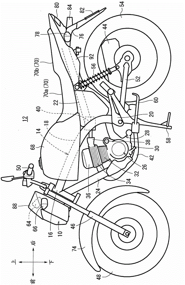
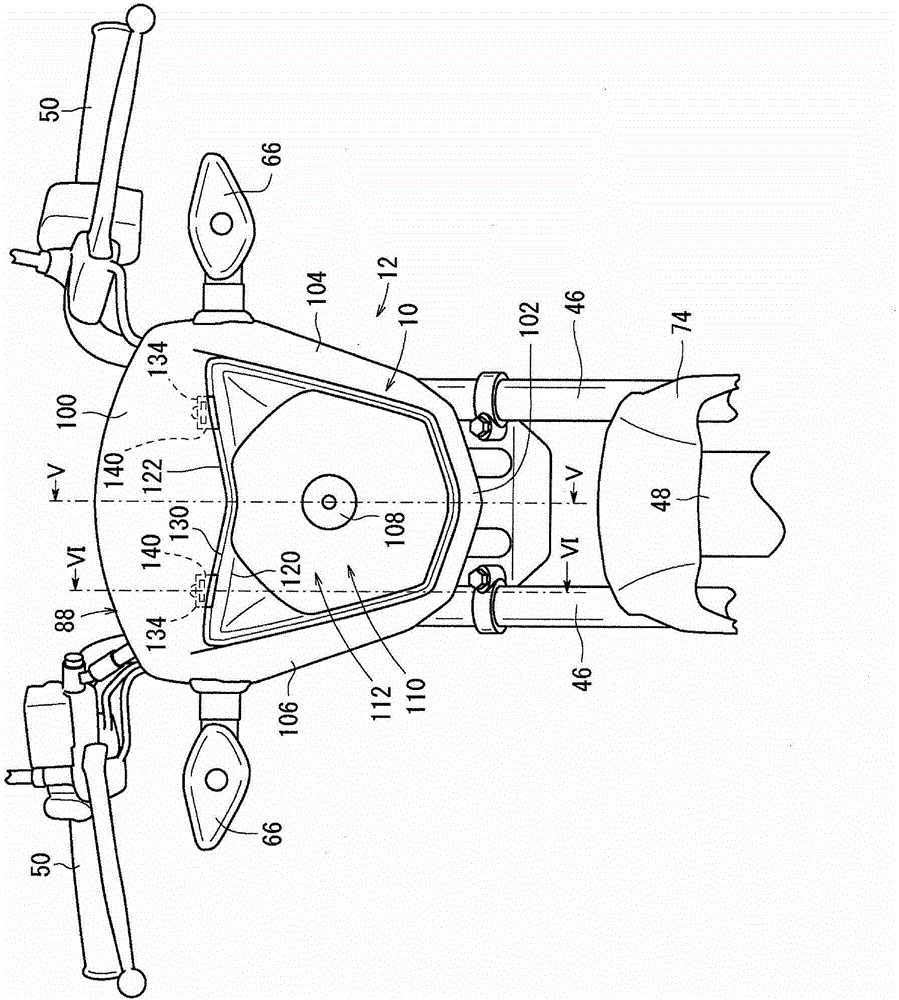
[0032] figure 1 It is a left side view of a motorcycle 12 as a straddle-type vehicle equipped with a light illuminator (headlight) 10 in this embodiment. In addition, in order to facilitate the understanding of the present invention, in the following description, unless otherwise specified, the figure 1 The front-rear and up-down directions are described based on the directions indicated by the middle arrows, and the left-right directions are described based on the directions seen by the driver sitting on the vehicle body.

[0033] The two-wheeled motorcycle 12 has a body frame 14 constituting the vehicle body. The body frame 14 has a head pipe 16 arranged at its front end, a main frame 18 extending obliquely from the head pipe 16 to the rear and downward, and a rear end portion connected to the ...


PUM


Abstract

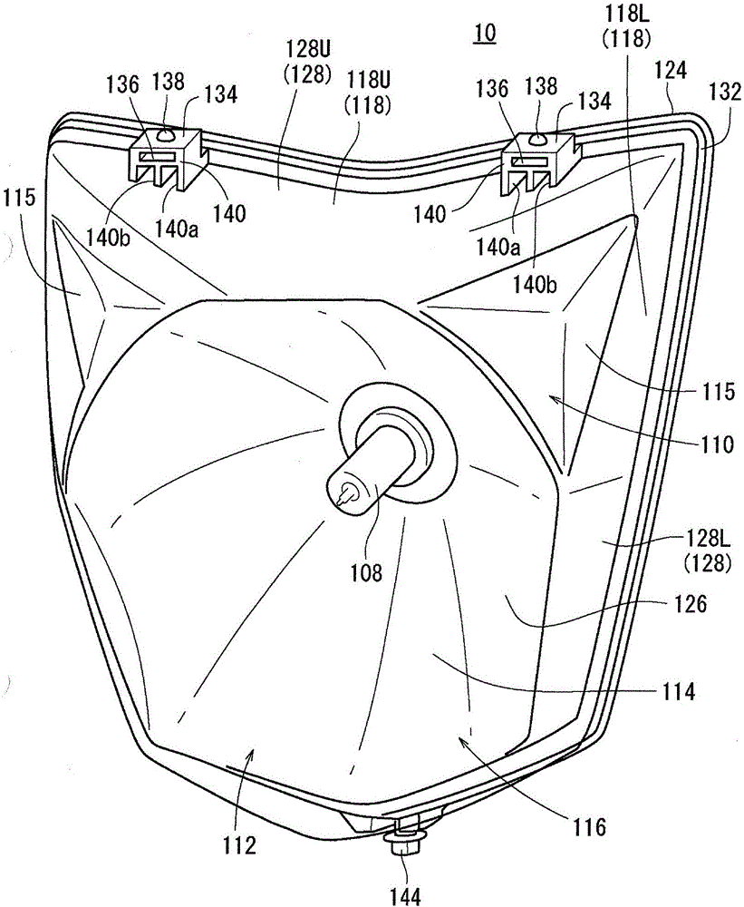
The invention provides a light irradiator supporting structure of straddle vehicle, and the structure can prevent deformation of a light irradiator cover without improving the rigidity of the light irradiator cover when impact load from the ground is received by the structure. Straddle vehicle (12) comprises the light irradiator (10) and the light irradiator cover (88) supported on a vehicle body frame (14). The light irradiator comprises a light source (108), a housing (110) supporting and covering the light source, and a lens. The top of the light irradiator (10) is provided with a rotation shaft portion (134) used for adjusting light axis. The housing is provided with a main body portion (116) and a cover portion (118U) formed in one body by extending backwards from the top edge portion (120U) of the main body portion. The lens is provided with a main body portion (126) and a cover portion (128U) formed in one body by extending backwards from the top edge portion (130U) of the main body portion.

Description

technical field [0001] The present invention relates to a light illuminator support structure (or installation structure, holding structure) of a straddle vehicle capable of alignment adjustment (aiming, optical axis adjustment). Background technique [0002] In the following patent document 1, a structure capable of alignment adjustment (optical axis adjustment) of the light illuminator is disclosed. In this structure, a pivot is provided on the upper part of the reflector of the light illuminator, and the pivot is inserted into the The light irradiator is supported by the rear cover in the engagement recessed portion of the rear cover that covers the light irradiator from the rear and can be rocked, and the optical axis of the light irradiator can be adjusted by the rocking. [0003] Since the light irradiator is supported on the rear cover in a rockable manner, in order to ensure the swing space of the light irradiator, it is necessary to leave a relatively large space be...

Claims


Application Information

Patent Timeline
Patent Type & Authority Patents(China)
IPC IPC(8): B62J6/02F21V17/10
Inventor 真壁知也
Owner HONDA MOTOR CO LTD
Learn More