Method for welding T-shaped movable beam for deformed glass machining system

A processing system and special-shaped glass technology, which is applied in welding equipment, metal processing equipment, manufacturing tools, etc., can solve problems such as difficulty in applying high-precision welding operations, difficulty in ensuring horizontal accuracy, and affecting welding quality, so as to achieve ideal processing effects and structural Good rigidity and beautiful processing effect

Inactive Publication Date: 2015-06-03
LUOYANG BAOHUAN NUMERICAL CONTROL PRECISE EQUIP MFG CO LTD
View PDF10 Cites 0 Cited by
  • Summary
  • Abstract
  • Description
  • Claims
  • Application Information

AI Technical Summary

Problems solved by technology

[0004] The welding grooves of the existing welding process are generally V-shaped and U-shaped grooves, and the grooves are all greater than 40 degrees, and conventional parameters are used. This method has no strict requirements on welding errors. Although it meets the requirements of welding depth, However, welding fluid splashes will be generated during welding, and the operation is unsafe. Pores are also likely to be generated in the weld, which affects the quality. Because of the large groove angle and wide gap to be filled, the horizontal accuracy is difficult to guarantee, and the number of welding times is large. Large amount, time-consuming, material-intensive, affecting welding quality, difficult to apply to high-precision welding operations

Method used


Image

  • Method for welding T-shaped movable beam for deformed glass machining system
  • Method for welding T-shaped movable beam for deformed glass machining system
  • Method for welding T-shaped movable beam for deformed glass machining system

Examples


Embodiment 1

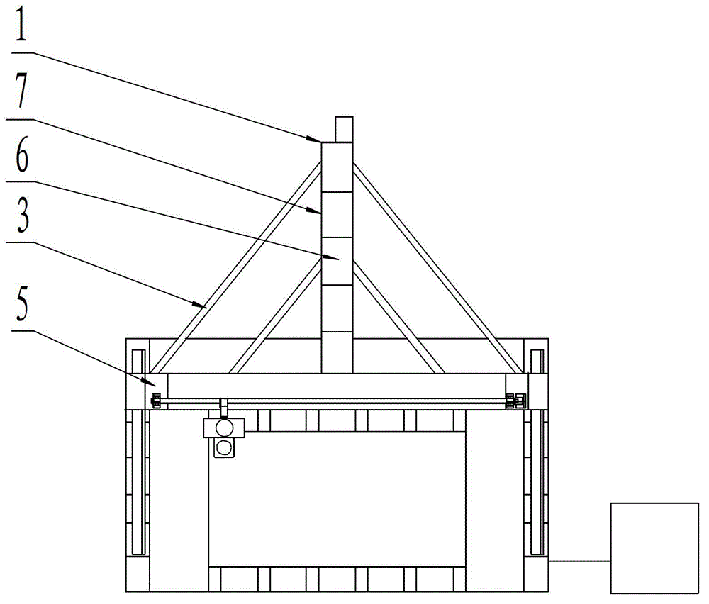
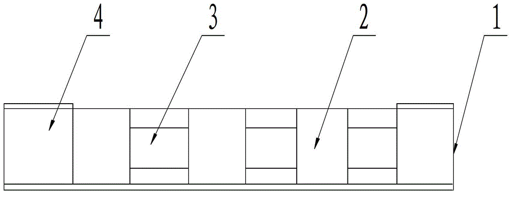
[0025] The T-shaped mobile beam adopts an overall frame structure, which is welded by rib plate 2, channel steel 3, square tube 4, bottom plate 6, vertical plate 6, and reference plane. The rib plate 2, channel steel 3, square tube 4, The thickness of the bottom plate 6 and the vertical plate 7 are both 10mm-15mm. The rib plate 2 is welded into a rectangular rib plate 2 on the automatic rotary welding equipment, and the channel steel 3 is welded into a rectangular channel steel 3 on the automatic rotary welding equipment. 3. The welding seam is Y-shaped during welding, and the rectangular rib plate 2 and the rectangular channel steel 3 are welded into a rectangular long column on the automatic rotary welding equipment. When the rectangular rib plate 2 and the rectangular channel steel 3 are welded, the weld seam is Y-shaped. When welding on automatic rotary welding equipment, resistance welding is used, and then carbon dioxide gas shielded double-gun symmetrical welding is used...

Embodiment 2

[0027] The welding method of the rectangular ribbed plate 2 is to clean the surfaces to be welded of the four ribbed plates 2, fix the four ribbed plates 2 in a rectangular shape on the automatic rotary welding equipment, and press the welding surface of the two adjacent ribbed plates 2 at 90 Align the four ribs 2 in a rectangular shape, the gap between the welds to be welded is 0.1mm-2mm, the resistance welding process parameters are preferably: welding wire diameter 1.5mm-2.0mm, welding current 400A-500A, welding voltage The power is 32V-36V, the power-on time is 2min, and the four welds are spot-welded by resistance welding, and then the symmetrical welds are grounded at the same time, welding to 2 / 3 of the weld bead, and the four welds are finished. Finally, use carbon dioxide gas protection double gun symmetrical welding to carry out horizontal welding on the symmetrical weld seam at the same time. The horizontal welding process parameters are preferably: the diameter of t...

Embodiment 3

[0029] The welding method of rectangular channel steel 3 is to clean the surfaces to be welded of two pieces of channel steel 3, and process the weld seam on the surface to be welded into a Y shape, the gap between the weld seams is 0.1mm-2mm, and the slope of the Y-shaped weld seam The mouth angle is 6 degrees to 15 degrees, the height of the blunt edge is 1mm-3mm, two pieces of channel steel 3 are fixed on the automatic rotary welding equipment in a rectangular shape, and the surfaces to be welded are aligned. The resistance welding process parameters are preferably: the diameter of the welding wire is 1.0mm-1.5mm, the welding current is 400A-500A, the welding voltage is 32V-36V, and the power-on time is 2min. Use resistance welding to spot weld two welds, and use resistance welding to weld symmetrical weld grooves at the same time Bottom welding, welded to 2 / 3 of the weld groove, after the bottom welding of the two welds of rectangular channel steel 3 is completed, use carbo...


PUM

PropertyMeasurementUnit
thicknessaaaaaaaaaa
diameteraaaaaaaaaa
angleaaaaaaaaaa

Abstract

The invention discloses a method for welding a T-shaped movable beam for a deformed glass machining system. The T-shaped movable beam consists of a longitudinal stepping / servo mechanism longitudinal beam, a rib plate, channel steel, a square pipe, a longitudinal stepping / servo mechanism transverse beam, a bottom plate and a vertical plate, and is characterized in that the rib plate, the channel steel, the square pipe, the bottom plate and the vertical plate are 10-15 millimeters in thickness. Automatic rotary welding equipment is adopted, electric resistance welding and carbon dioxide gas protection dual-gun balanced welding are adopted for welding, the welding way of the electric resistance welding includes point welding and backing welding, and the welding way of the carbon dioxide gas protection dual-gun balanced welding includes transverse welding and flat welding, so that the T-shaped movable beam has the advantages of high welding speed, no air hole in welding lines, small bevel angle, high quality, reliable performance and high mechanical performance of joints, and horizontal accuracies of upper and lower horizontal planes are ensured; and when the deformed glass machining system runs, the T-shaped movable beam has ideal synchronizing performance, is firm and highly rigid in structure, runs more stably, and can bear large-torque grinding without being deformed.

Description

technical field [0001] The invention relates to the field of welding technology, in particular to a welding method for a T-shaped moving beam of a special-shaped glass processing system. Background technique [0002] At present, the moving beam of special-shaped glass processing equipment on the existing market is driven by two sets of driving mechanisms. When the two sets of driving mechanisms operate at the same time, the synchronization is difficult to control, and the operation stability is poor, which affects the dimensional accuracy of high-grade glass products. [0003] A T-shaped moving beam for special-shaped glass processing system is now designed. The T-shaped moving beam adopts an integral frame structure, which is welded by ribs, channel steel, square tubes, bottom plates, vertical plates, and reference planes. The special-shaped glass processing system During operation, the T-shaped moving beam has ideal synchronous performance, strong and rigid structure, more...

Claims


Application Information

Patent Timeline
Patent Type & Authority Patents(China)
IPC IPC(8): B23K28/02
Inventor 李治伟肖淼鑫
Owner LUOYANG BAOHUAN NUMERICAL CONTROL PRECISE EQUIP MFG CO LTD
Why Eureka
Try Eureka