
Apparatus for detecting and measuring cylindrical surfaces on fireproof ceramic components in metallurigal applications

A technology of ceramics and components, which is applied in the field of devices with columnar surfaces, can solve problems such as inaccurate results, and achieve the effect of preventing melt-through

Inactive Publication Date: 2013-10-09
REFRACTORY INTELLECTUAL PRORERTY GMBH & CO KG
View PDF9 Cites 0 Cited by
  • Summary
  • Abstract
  • Description
  • Claims
  • Application Information

AI Technical Summary

Problems solved by technology

Here again only very imprecise results are obtained

Method used


Image

  • Apparatus for detecting and measuring cylindrical surfaces on fireproof ceramic components in metallurigal applications
  • Apparatus for detecting and measuring cylindrical surfaces on fireproof ceramic components in metallurigal applications
  • Apparatus for detecting and measuring cylindrical surfaces on fireproof ceramic components in metallurigal applications

Examples


Embodiment Construction

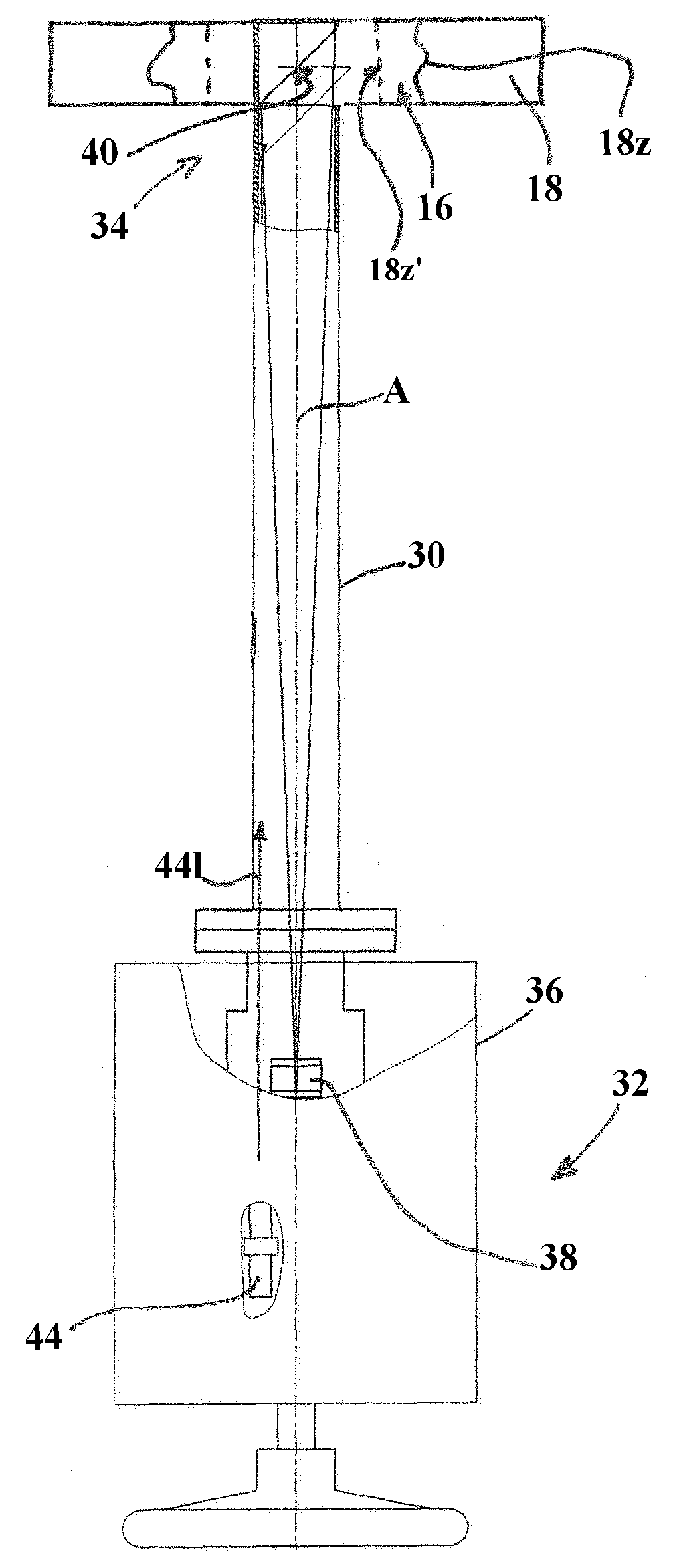
[0039] The figure shows a cylindrical measuring tube 30 with a first end 32 (the so-called "cold end") and a second end 34 (the so-called "hot end").

[0040] The measuring tube 30 widens at a first end 32 and accommodates in this section a camera 38 , here a single-lens reflex camera.

[0041] Camera 38 is aligned in the direction of reflective surface 40 , which is located within second end 34 of measuring tube 30 and extends here at an angle of 45° to longitudinal center axis A of measuring tube 30 .

[0042]The measuring tube 30 has corresponding openings 42 in adjacent wall sections, so that parts of the cylindrical surface 18 o of the slide 18 can be detected by means of the camera 38 via the reflective surface 40 .

[0043] exist figure 2 The course of the cylindrical surface of the new slide is shown in dashed lines (18z'), while the solid line (18z) shows exemplary states of wear which are to be detected and evaluated by means of the device according to the inventio...


PUM


Abstract

The apparatus has a cylindrical measuring pipe (30) formed in a peripheral portion that lies opposite to a reflection surface (40), so that a camera (38) detects a part of a cylindrical upper surface (18z) of an adjacent refractory ceramic component (18) with focal length between an objective and a reflection surface. The part of the upper surface runs along a radial distance, and is detected by the camera. A distance measuring unit (44) is arranged in the pipe at a distance between points or surface sections on the part of the upper surface at a reference point.

Description

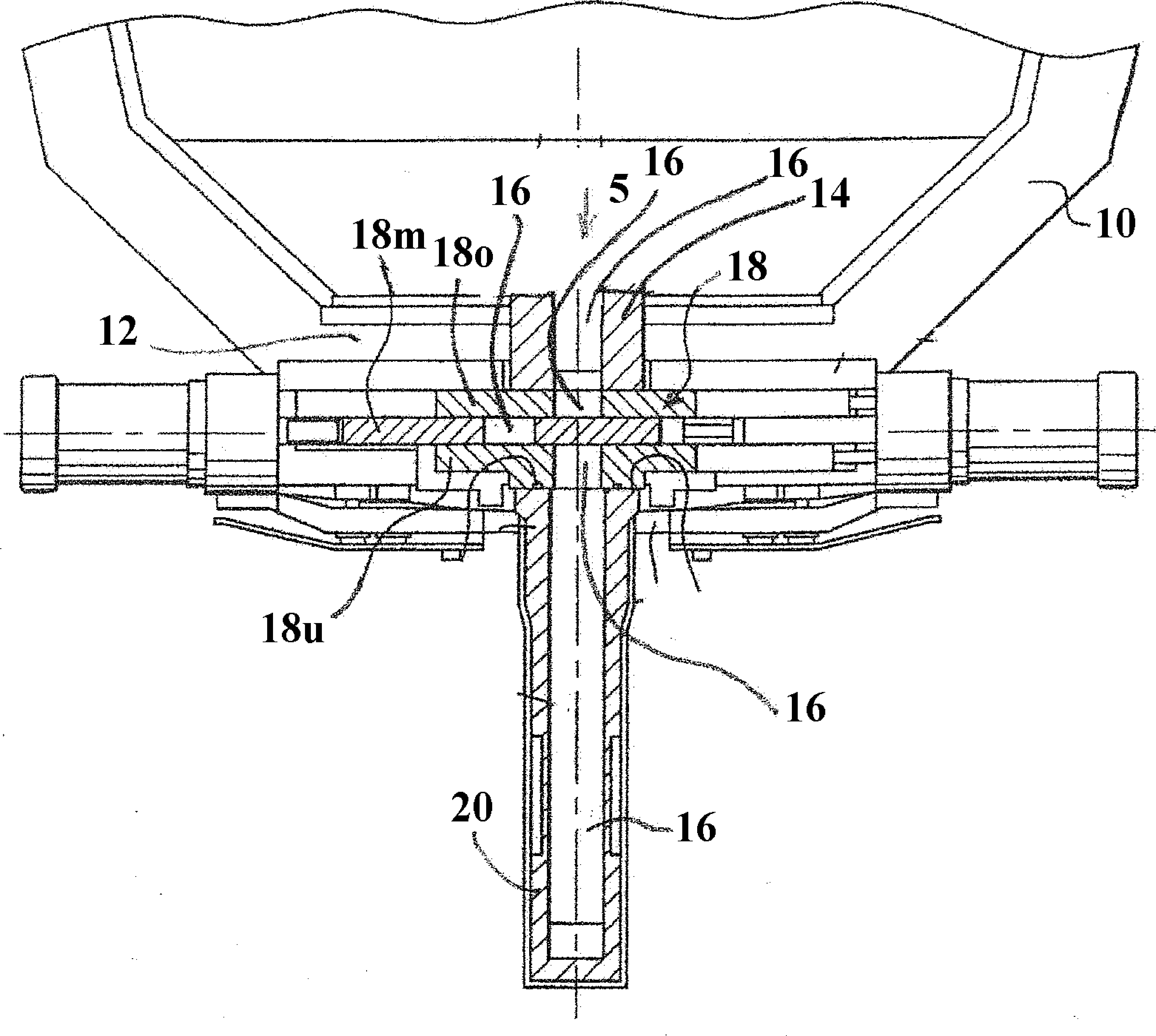
technical field [0001] The invention relates to a device for detecting and measuring cylindrical surfaces on refractory ceramic components in metallurgical applications. Background technique [0002] figure 1 Typical metallurgical applications are shown without limiting the scope of the invention. A metallurgical vessel 10 with a refractory-lined bottom 12 can be seen, in which a substantially cylindrical refractory ceramic discharge opening 14 is arranged, which has a central flow-through opening 16 through which the metal melt The metallurgical container 10 flows through the flow-through opening into downstream equipment. [0003] Here, a sliding closure (Schieberverschluss) 18 with an upper slide 18o, a middle slide 18m and a lower slide 18u adjoins the discharge opening 14 in the flow direction of the melt (arrow S), the submerged discharge opening ( Tauchausguss) 20 is connected to the lower slide. Corresponding to the flow-through line 16, all the components mentio...

Claims


Application Information

Patent Timeline
Patent Type & Authority Applications(China)
IPC IPC(8): G01B11/12
CPCH04N7/183G01B11/12
Inventor G.保罗
Owner REFRACTORY INTELLECTUAL PRORERTY GMBH & CO KG
Learn More