Belt conveyor can be loaded with power isolation flexible start speed regulating device

A belt conveyor and flexible start technology, applied in the direction of conveyors, transmission devices, fluid transmission devices, etc., can solve the problems of design and cost control adverse effects, reduce load acceleration torque, and belt conveyor adverse effects, etc., to achieve Reduce the difficulty of technical realization, reduce the braking torque requirement, and improve the effect of continuous operation performance

Active Publication Date: 2016-02-10
沈阳中煤工程技术有限公司
View PDF8 Cites 6 Cited by
  • Summary
  • Abstract
  • Description
  • Claims
  • Application Information

AI Technical Summary

Problems solved by technology

During the operation of the belt conveyor, there are often no-load or light-load operating conditions. Under such conditions, the drive motor system of the belt conveyor has high energy consumption loss and low power factor, resulting in huge Energy waste
In order to solve the above problems, the existing technology usually adopts the structure of installing an overrunning clutch on the low-speed shaft of the belt conveyor reducer to reduce the energy consumption of the motor system and improve the power factor of the motor system. However, due to the The low-speed shaft torque of the conveyor reducer and the nominal torque of the overrunning clutch do not overlap, so that in practical applications, the high-torque belt conveyor usually cannot select a suitable nominal torque overrunning clutch; If a suitable overrunning clutch is selected for the torque belt conveyor, it will also have an adverse effect on the design and cost control due to the oversized overrunning clutch; in addition, the installation of an overrunning clutch on the low-speed shaft of the belt conveyor reducer can stop the motor from running. The drive unit is in the overrunning condition, the torque of the belt conveyor will not be reversely transmitted to the motor, but the motor will produce a positive torque impact when it is restarted and put into operation, which will have an adverse effect on the belt conveyor
[0003] The utility model patent with the application number 200620093870.,9 proposed by the applicant discloses a flexible start-up speed control device for belt conveyors, which includes a speed control transmission unit and an automatic control unit with a touch monitor. The main point is that the inner end of the flow channel of the pump wheel working chamber in the rotor body of the speed-regulating fluid coupling of the speed-regulating transmission unit is provided with an oil inlet, and the inlet end of the flow channel of the turbine working chamber is provided with a buffer guide flow channel, The oil drain screw plug connected to the working chamber is installed in the circumferential direction of the rotating shell, the pull rod of the guide tube control device and the crank of the electric actuator are hinged by connecting rods, and the PID module of the automatic control unit based on PLC and the signal of the speed regulating transmission unit The sensing unit forms a closed-loop adjustment circuit. This device can enable the drive motor to start without load and reduce the acceleration torque of the load. However, this device cannot achieve the purpose of belt conveyor power isolation or re-introduction under running conditions, and there are still When the belt conveyor runs under no-load or light-load conditions during operation, it cannot cut off the power input of some motors, resulting in unnecessary waste of energy. This problem is caused by the use of belt conveyors in ports and mines. The technical problems that have been hoped to be solved on occasions

Method used


Image

  • Belt conveyor can be loaded with power isolation flexible start speed regulating device
  • Belt conveyor can be loaded with power isolation flexible start speed regulating device
  • Belt conveyor can be loaded with power isolation flexible start speed regulating device

Examples


Embodiment Construction

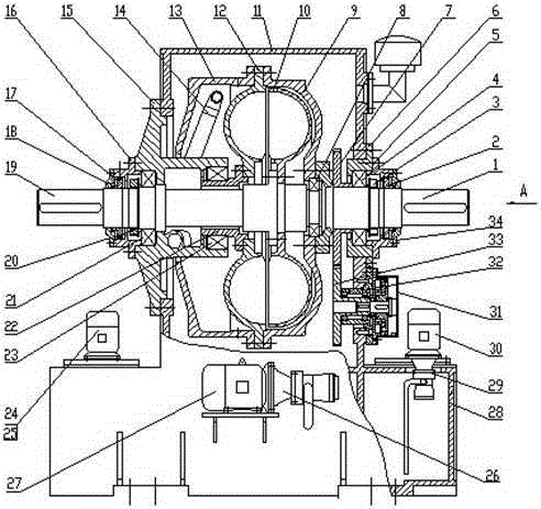
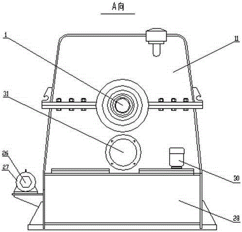
[0045]Such as figure 1 and figure 2 Shown, the present invention comprises box body 28 and box cover 11, and box body 28 and box cover 11 are fixedly connected together with bolts, and left and right 2 circular holes are processed on the sub-case surface of box body 28 and box cover 11, and The left end face of the left round hole is equipped with an oil discharge cavity 15, the oil discharge cavity 15 is fixedly connected with the box body 28 and the case cover 11 with bolts, and a turbine shaft 19 is installed in the oil discharge cavity 15, and the turbine The shaft 19 is equipped with a turbine bearing 21, a second round nut 20, a first left end cover 16, a turbine tachometer gear 17 and a second left end cover 18, and the first left end cover 16 and the oil discharge cavity 15 on the right are connected by bolts For fixed connection, the shoulder end surface on the right side of the first left end cover 16 is pressed against the left end surface of the outer ring of the...


PUM


Abstract

A flexible start speed adjusting device capable of realizing belt-type conveyor on-load power isolation overcomes the defects that in an existing belt-type conveyor multi-motor driving system, the working condition of non-load operation or light-load operation often occurs, and energy is wasted. The flexible start speed adjusting device is characterized in that brake mounting holes are machined in one side, provided with a pump wheel axle, of a box body, an electro-magnetic brake is installed through a brake bearing seat, and a driven gear which is matched with a driving gear is installed on a brake shaft of the electro-magnetic brake. The flexible start speed adjusting device has the advantages that the multi-motor driven belt-type conveyor on-load power isolation function is realized, the purpose of saving energy is achieved, the type selection range of the electro-magnetic brake is small, the technology realizing difficulty is low, an electromagnetic brake body is low in manufacturing cost, the purposes that torque impact of equipment during the motor power isolation process or the motor power reapplication process is reduced, and when a certain motor in the driving system of the bet-type conveyor fails, the motor can be turned off under the condition that loads allow and the normal work and operation of the belt-type conveyor are not influenced are realized, and the continuous operation capacity of the conveyor is improved.

Description

technical field [0001] The invention belongs to the technical field of hydraulic transmission, and in particular relates to a multi-machine drive applied to a belt conveyor, so that the belt conveyor can realize on-load power isolation or a re-introduced belt conveyor can carry on-load power isolation without stopping. Soft start governor. Background technique [0002] The belt conveyor is the main equipment for transporting bulk materials. The driving system of the large-capacity, long-distance belt conveyor usually consists of two or more motors. During the operation of the belt conveyor, there are often no-load or light-load operating conditions. Under such conditions, the drive motor system of the belt conveyor has high energy consumption loss and low power factor, resulting in huge Energy waste. In order to solve the above problems, the existing technology usually adopts the structure of installing an overrunning clutch on the low-speed shaft of the belt conveyor redu...

Claims


Application Information

Patent Timeline
Patent Type & Authority Patents(China)
IPC IPC(8): F16H41/24F16H41/30B65G23/26B65G23/24
Inventor 刘炽彭程韦胜杰
Owner 沈阳中煤工程技术有限公司
Why Eureka
Try Eureka