Eureka AIR delivers breakthrough ideas for toughest innovation challenges, trusted by R&D personnel around the world.

Polycrystalline silicon ingotting furnace and ingotting method thereof

A technology of polysilicon ingot casting furnace and ingot casting, which is applied to the growth of polycrystalline materials, chemical instruments and methods, crystal growth, etc., can solve the problems of slow heating rate of silicon liquid, shortened thermal field life, and limitation of silicon material temperature rise, etc., to achieve The effect of shortening ingot casting time, increasing production capacity, and large process window

Active Publication Date: 2013-10-09
YINGLI ENERGY CHINA
View PDF10 Cites 9 Cited by
  • Summary
  • Abstract
  • Description
  • Claims
  • Application Information

AI Technical Summary

Problems solved by technology

The recrystallization layer separates the silicon material in the crucible into upper and lower parts, the upper part is liquid silicon, and the lower part is massive solid silicon. The surface of the upper part of the silicon liquid layer forms a mirror effect, which acts on the radiant light of the heater and reflects the radiation radiated by the heater upward. The thermal energy causes the silicon liquid to heat up slowly, and the temperature rise of the silicon material at the bottom of the crucible is also greatly restricted.
[0007] (3) In order to increase the production capacity of the ingot furnace, the only way to accelerate the melting of silicon material is to increase the power of the heater. The increase in the power of the heater will cause the temperature in the upper area of ​​the thermal field to rise continuously, and a large amount of silicon will be formed in the furnace. Silicon vapor and other impurity gases volatilized, these gases undergo a large number of chemical reactions near the heater, causing great damage to the heater and graphite parts in the upper area of ​​the thermal field, seriously reducing the life of the thermal field

Method used


Image

  • Polycrystalline silicon ingotting furnace and ingotting method thereof
  • Polycrystalline silicon ingotting furnace and ingotting method thereof
  • Polycrystalline silicon ingotting furnace and ingotting method thereof

Examples


Embodiment Construction

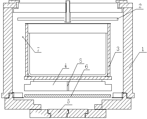
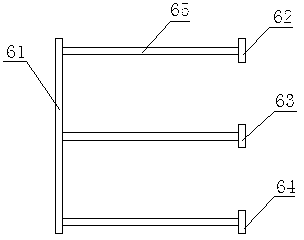
[0029] Such as figure 1 As shown, a polysilicon ingot furnace includes a furnace body insulation layer 1, a top heater 2, a quartz crucible 3, a cooling platform 4 and a heat dissipation window 5, and also includes a bottom heater 6, which is located at the bottom Describe the underside of the cooling platform 4. Such as figure 2 As shown, the bottom heater 6 includes a common terminal 61, an A-phase electrode 62, a B-phase electrode 63, a C-phase electrode 64 and a heater 65, and the A-phase electrode, B-phase electrode and C-phase electrode pass through the heater 65 Connect to the common terminal 61.

[0030] A polysilicon ingot casting method, comprising the steps of heating, melting, directional crystallization, annealing and cooling, characterized in that the heating step is:

[0031] (1) The duration is 9-11 minutes, set the power output of the top heater to 10%, set the power output of the bottom heater to 10%, vacuum mode, the air intake is zero, and the heater i...


PUM


Abstract

The invention discloses a polycrystalline silicon ingotting furnace and an ingotting method thereof, relating to the technical field of equipment for preparing uniform polycrystalline silicon with a certain structure. The ingotting furnace comprises a furnace body insulating layer, a top heater, a quartz crucible, a heat-dissipation platform, a heat-dissipation window and a bottom heater. The bottom heater is located on the lower side of the heat-dissipation platform. The bottom heater and the top heater are controlled by independent transformers, and are adjusted separately. The rate power of the bottom heater is 5kw-100kw. The bottom heater is started in the heating and smelting period during a running process of the ingotting furnace, and is stopped completely during a crystallization process of silicon liquid, so that the temperature of silicon material at the bottom of the crucible quickly rises by the smelting of the silicon material, thereby reducing the smelting duration of the silicon material and improving the productivity of the ingotting furnace.

Description

technical field [0001] The invention relates to the technical field of preparing a uniform polysilicon device with a certain structure. Background technique [0002] At present, the photovoltaic industry is developing rapidly. Due to its high production capacity and stable quality of cast polycrystalline and quasi-monocrystalline silicon ingots, polycrystalline ingot furnaces are widely used in the photovoltaic power generation industry. During the polycrystalline ingot casting, the primary silicon material is carried in a quartz crucible, and after five processes of heating, melting, directional crystallization, annealing, and cooling in the ingot casting furnace, the high-purity polycrystalline silicon material is finally grown into a material for the production of solar cells. of polycrystalline silicon ingots. [0003] There are many new structures of thermal field heaters and bottom cooling methods in the existing polycrystalline ingot casting furnace. When designing t...

Claims


Application Information

Patent Timeline
IPC IPC(8): C30B28/06C30B29/06
Inventor 潘家明陈艳涛田伟华
Owner YINGLI ENERGY CHINA
Why Eureka
Eureka Blog
Learn More