A semi-controlled active injection current type high-voltage DC circuit breaker and its realization method
A technology of injecting current and high-voltage direct current, which is applied in the direction of direct current network circuit devices, circuit devices, electrical components, etc., can solve the problems that the breaking time cannot meet the multi-terminal flexible direct current transmission system, the technical difficulty is high, and the manufacturing cost is high, so as to achieve easy implementation and Expansion, reduction of manufacturing cost, effect of small number
- Summary
- Abstract
- Description
- Claims
- Application Information
AI Technical Summary
Problems solved by technology
Method used
Image
Examples
Embodiment 1
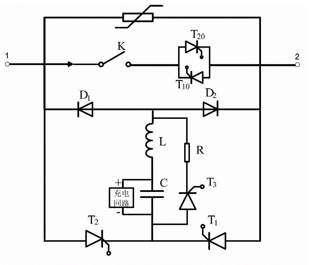
[0044] The method implements different operations for the normal operation of the DC system and the occurrence of a ground short-circuit fault; when a ground short-circuit fault occurs, the isolation of the DC power supply DC and the capacitor C is realized by controlling the full control device in the charging circuit.
[0045] The diode valve series branch and the thyristor valve series branch are connected in parallel to form two bridge arms of the bridge circuit respectively, and the realization method is as follows:
[0046] (1) When the DC system is running normally, the high-speed mechanical switch K is closed, and the thyristor T 20 and T 10 Keep triggering. flow past figure 1 When the current flows in the direction indicated by the middle arrow, the thyristor T 20 In the conduction state, the thyristor valve T 1 , T 2 , T 3 To keep the latch, the charging circuit fully controls the device and the thyristor valve T 6 Trigger to charge the capacitor C. Due to th...
Embodiment 2
[0052] Another embodiment of the resistance-thyristor valve series branch circuit provided by the present invention is as image 3 As shown, when the series branch of the diode valve is replaced by the series branch of the thyristor valve, the realization method is as follows:
[0053] (1) When the DC system is running normally, the high-speed mechanical switch K is closed, and the thyristor T 20 and T 10 Keep triggering. flow past figure 1 When the current flows in the direction indicated by the middle arrow, the thyristor T 20 In the conduction state, the thyristor valve T 1 , T 2 , T 3 , T 4 , T 5 To keep the latch, the charging circuit fully controls the device and the thyristor valve T 6 Trigger to charge the capacitor C. Due to the low withstand voltage required by the anti-parallel thyristors, generally speaking, a group of thyristors can meet the requirements. Therefore, when the system is operating normally, the inventive circuit breaker produces very little...
PUM
 Abstract
Description
Claims
Application Information
 - R&D
- Intellectual Property
- Life Sciences
- Materials
- Tech Scout
- Unparalleled Data Quality
- Higher Quality Content
- 60% Fewer Hallucinations
Browse by: Latest US Patents, China's latest patents, Technical Efficacy Thesaurus, Application Domain, Technology Topic, Popular Technical Reports.
© 2025 PatSnap. All rights reserved.Legal|Privacy policy|Modern Slavery Act Transparency Statement|Sitemap|About US| Contact US: help@patsnap.com


