
Pump fiber combiner manufacturing method for large power fiber laser

A fiber laser and pump fiber technology, applied in the field of optical fiber, can solve the problems of large signal light loss, increased temperature of the beam combiner, low pump light absorption rate, etc., to achieve enhanced anti-reflection ability, small signal insertion loss, The effect of high pumping efficiency

Active Publication Date: 2013-10-02
DANYANG JUCHEN OPTOELECTRONICS TECH
View PDF4 Cites 18 Cited by
  • Summary
  • Abstract
  • Description
  • Claims
  • Application Information

AI Technical Summary

Problems solved by technology

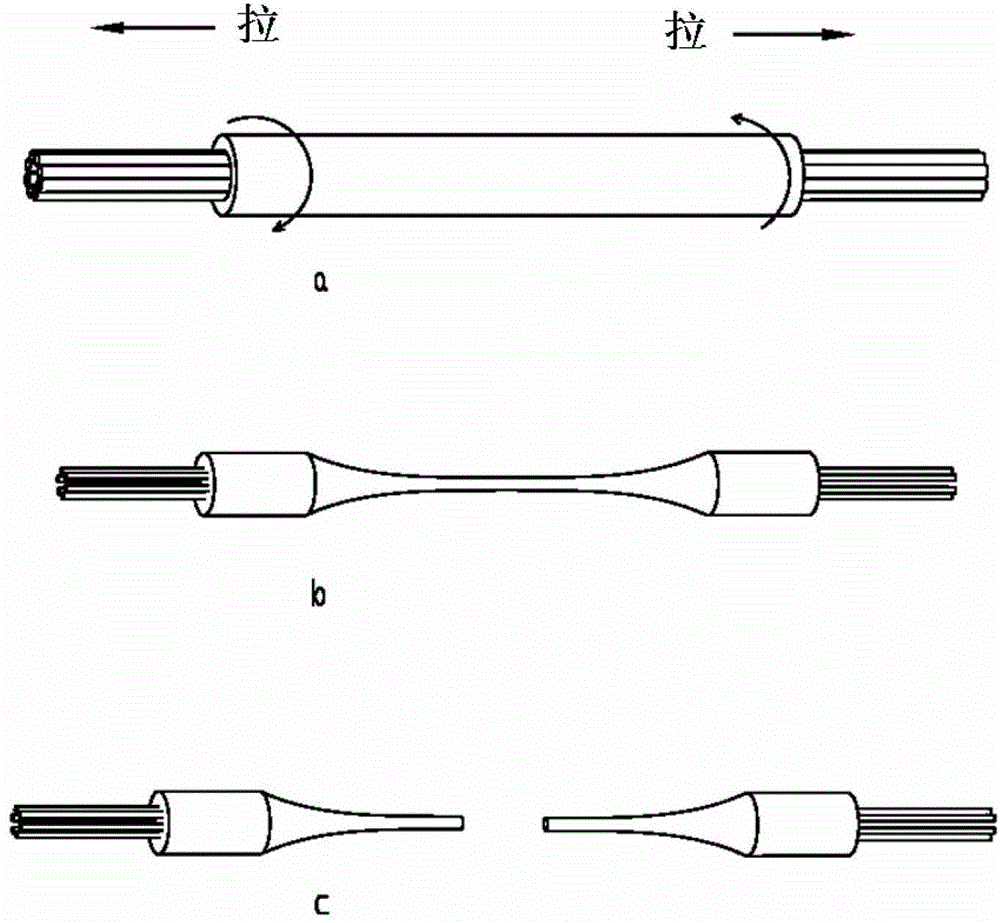
[0004] This beam combiner is essentially an end-pumping device, which has the following disadvantages: 1. In the process of melting and tapering, the pump fiber and signal fiber are deformed due to torsional force, and the loss of signal light is relatively large , usually the insertion loss is 0.5dB; in a kilowatt-class laser, this is equivalent to a power loss of 100W, resulting in a high temperature rise of the beam combiner, which seriously affects the beam quality, and even damages the optical fiber and components
2. Since the pump fiber and the signal fiber are twisted together, there is no waveguide for the pump light, so the absorption rate of the pump light is low, only about 90%
3. Because it is an end-pumped beam combiner, the signal light reflected from the output end of the fiber laser can easily enter the pump diode, causing damage to the semiconductor diode

Method used


Image

  • Pump fiber combiner manufacturing method for large power fiber laser
  • Pump fiber combiner manufacturing method for large power fiber laser
  • Pump fiber combiner manufacturing method for large power fiber laser

Examples


Embodiment 1

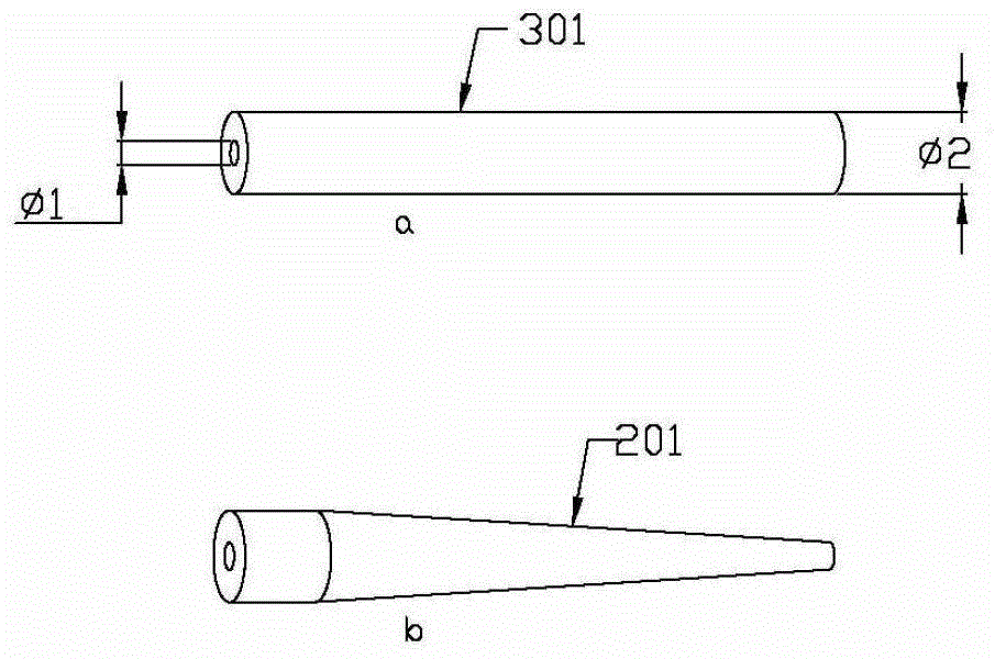
[0028] Depend on image 3 Known, the manufacture method of the pump fiber beam combiner that is used for high-power fiber laser, comprises the following steps: 1, by image 3 a know, choose a section of quartz capillary 301, its inner diameter φ1 is just equal to the outer diameter of the inner cladding of the double-clad optical fiber, and the outer diameter φ2 of the quartz capillary depends on the number of pumping fibers required (such as 25 / 250 optical fiber, the inner diameter of the tube is 250 μm ; Such as 20 / 400 optical fiber, the inner diameter of the tube is 400μm).

[0029] 2. Use vertical polishing method to process quartz capillary, see image 3 b. Use a conical polishing machine to polish one end of the quartz capillary, and control the conical angle to 2θ to obtain image 3 The quartz capillary 201 shown in b has a conical shape at one end and a planar shape at the other end.

[0030] 3. Thread a plurality of pumping optical fibers 202 into a porous metal o...

Embodiment 2

[0034] Depend on Image 6 It is known that the manufacturing method of the pumping fiber combiner for high-power fiber lasers uses horizontal polishing to process the quartz capillary so that one end is conical, and the rest of the steps are the same as in Example 1.

Embodiment 3

[0036] Depend on Figure 7 It is known that the manufacturing method of the pump fiber combiner used for high-power fiber lasers is to put the cylindrical quartz capillary vertically into the hydrofluoric acid (HF) solution by hydrofluoric acid etching method, and slowly lift it to make the outer surface of the quartz capillary It is corroded into a conical shape, and one end of the processed quartz capillary is conical. In order to prevent the inner wall of the capillary from being corroded, it is necessary to coat an antiseptic on the inner wall of the capillary in advance; the remaining steps are the same as in Example 1.


PUM


Abstract

The invention relates to a pump fiber combiner manufacturing method for a large power fiber laser. The pump fiber combiner manufacturing method comprises steps of: 1), selecting a quartz capillary; 2), processing the quartz capillary; 3), tabulating; 4), welding; and 5), packaging. The pump fiber combiner manufacturing method realizes omission of a fusion tapering process, generates no fiber deformation, greatly reduces insertion loss and improves pump efficiency.

Description

technical field [0001] The invention belongs to the technical field of optical fibers and relates to a manufacturing method of a pumping optical fiber beam combiner used for high-power optical fiber lasers. Background technique [0002] In high-power fiber lasers, the pump beam combiner, also known as the power beam combiner, is a key device. The pump light emitted by multiple semiconductor lasers (LD) enters the inner package of the active double-clad fiber through the beam combiner. layer, and then gradually absorbed by the core, causing the signal light to be stimulated and amplified. [0003] There are two types of traditional pump light combiners, N×1 type and (N+1)×1 type, due to different structures. Below to figure 1 The (N+1)×1 type pump combiner shown is taken as an example, and its manufacturing process and working principle are introduced as follows: First, N pump fibers are tightly arranged around a signal fiber by means of a clamp , to form an optical fiber ...

Claims


Application Information

Patent Timeline
IPC IPC(8): G02B6/255
Inventor 李丰谈根林黄伟杨立梅
Owner DANYANG JUCHEN OPTOELECTRONICS TECH
Learn More