Cognitive radar detection device based on neural network
What is Al technical title?
Al technical title is built by PatSnap Al team. It summarizes the technical point description of the patent document.
A technology of cognitive radar and detection device, applied in measurement devices, radio wave measurement systems, reflection/reradiation of radio waves, etc. Effect
Inactive Publication Date: 2013-10-02
TAIYUAN UNIV OF TECH +1
View PDF3 Cites 4 Cited by
Summary
Abstract
Description
Claims
Application Information
AI Technical Summary
This helps you quickly interpret patents by identifying the three key elements:
Problems solved by technology
Method used
Benefits of technology
Problems solved by technology
[0002] Traditional radar detection devices usually use fixed transmission signals, and improve detection performance through adaptive processing at the receiving end and design of filtering algorithms. Since the detection performance of radar largely depends on the transmitted waveform, in the face of increasingly complex electromagnetic environments , multi-target background, when the environment of the fixed transmission waveform changes, it is difficult to obtain the desired effect only by the adaptive signal processing at the receiving end; VLSI technology and modern digital technology have laid the foundation for the direct synthesis of digital frequency waveforms, such as Phased array radar is capable of beam pointing change and waveform agility at the microsecond or hundreds of microsecond level, and has a high degree of self-adaptability and flexibility; at present, hardware technology has provided a good foundation for the self-adaptation of the radar system transmitter In this context, Simon Haykin of Canada once proposed a new system of intelligent radar system, that is, cognitive radar detection theory, which pointed out the intelligent development trend of radar in the future. However, the research on cognitive radar detection devices is still in its infancy. There are still many academic problems to be solved
Method used
Image
Click on the blue label to locate the original text in one second.
Reading with bidirectional positioning of images and text.
Examples
Embodiment 1
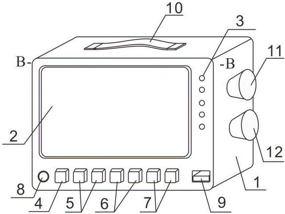
[0045] The measurement is used as follows:
[0046] (1) All parts of the cognitive radar detection device are in a quasi-working state;
[0047] (2) Place the cognitive radar device in front of the area to be detected, turn on the power, turn on the signal transmission controller and signal receiving controller, the green indicator light is on, and the cognitive radar starts to transmit signals;
[0048] (3) During the signal transmission process, if the red light of the indicator light is on, the device is not operating normally, and the reset switch is used to adjust;
[0049] (4) The cognitive radar transmits the detection waveform through the transmitting antenna, and after being reflected by the target, the receiving antenna receives the echo signal, and the cognitive radar extracts the environment and target motion parameters through the analysis of the echo signal, and displays them on the LCD screen in real time superior;
[0050] (5) Use the temperature and humidity...
PUM
Abstract
The invention relates to a cognitive radar detection device based on a neural network, whose main structure comprises a chassis, a liquid crystal display, indicator lamps, a power supply switch, reset switches, signal transmitting adjustment and control devices, signal receiving adjustment and control devices, a transmitting antenna, a receiving antenna, a circuit board, a direct current power supply and a circuit board circuit. Aiming at limitation of the traditional radar, the cognitive radar detection device uses the advantages of the neural network, information processing is performed on signals of the transmitting antenna and the receiving antenna, the neural network consists of nerve cells with nonlinear mapping functions, and information of the neural network is stored in a continuous weight coefficient by weight coefficient connection, so that the network has very high fault tolerance; information loss is reduced; self-organizing and the adaptivity of the neural network are high; the recognition capability is improved; the neural network, digital signal processing, and digital information collection, receiving and processing are accomplished by a computer program, so that informatization, programming and automation of the device are achieved; and as a very ideal cognitive radar detection device based on the neural network, the device is advanced in design, compact in structure and accurate in measurement data, and can be widely applied to various industrial detection fields.
Description
technical field [0001] The invention relates to a neural network-based cognitive radar detection device, which belongs to the technical field of design and manufacture of electronic measuring instruments. Background technique [0002] Traditional radar detection devices usually use fixed transmission signals, and improve detection performance through adaptive processing at the receiving end and design of filtering algorithms. Since the detection performance of radar largely depends on the transmitted waveform, in the face of increasingly complex electromagnetic environments , multi-target background, when the environment of the fixed transmission waveform changes, it is difficult to obtain the desired effect only by the adaptive signal processing at the receiving end; VLSI technology and modern digital technology have laid the foundation for the direct synthesis of digital frequency waveforms, such as Phased array radar is capable of beam pointing change and waveform agility...
Claims
Application Information
Patent Timeline
Application Date:The date an application was filed.
Publication Date:The date a patent or application was officially published.
First Publication Date:The earliest publication date of a patent with the same application number.
Issue Date:Publication date of the patent grant document.
PCT Entry Date:The Entry date of PCT National Phase.
Estimated Expiry Date:The statutory expiry date of a patent right according to the Patent Law, and it is the longest term of protection that the patent right can achieve without the termination of the patent right due to other reasons(Term extension factor has been taken into account ).
Invalid Date:Actual expiry date is based on effective date or publication date of legal transaction data of invalid patent.