
Modular sensor and manufacturing technique thereof

A manufacturing process and sensor technology, applied in the field of sensors, can solve the problems of poor product design flexibility, poor product versatility, broken and plugged PIN pins, and no signal detected by the sensor, so as to avoid damage to electronic components, ensure firm positioning, and ensure The effect of sensing breath

Active Publication Date: 2013-10-02
UNITED AUTOMOTIVE ELECTRONICS SYST
View PDF6 Cites 8 Cited by
  • Summary
  • Abstract
  • Description
  • Claims
  • Application Information

AI Technical Summary

Problems solved by technology

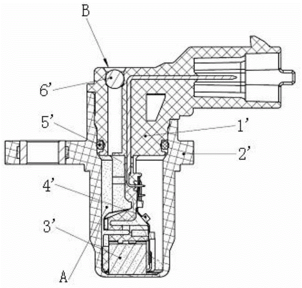
[0007] In the sensor structure of the bracket shell assembly type, it is easy to have a gap between the bracket sensing head (that is, the Hall chip 3') and the shell 2', so that the sensor cannot detect the signal or the sensor head squeezes the shell 2', causing the shell head bulge or even rupture
If the patent with publication number CN2896225Y is used to accurately control the gap between the sensor head of the bracket and the shell through the U-shaped groove structure, the circuit board assembly must use a flexible circuit board assembly, so that the cheaper hard circuit cannot be used board assembly, resulting in increased production costs, and secondly, the flexible circuit board assembly not only needs manual assembly, but also the welding of the flexible circuit board assembly and the plug-in PIN pin must be welded by hand and cannot be welded by machine, resulting in a decrease in product reliability
In addition, the sealing O-ring 5' between the bracket 1' and the shell 2' will age and lose its sealing performance after high temperature and durability, resulting in leakage
Adopting the epoxy resin curing structure in the invention patent with the publication number CN101008660A may cause the epoxy resin to cover the electronic components on the flexible circuit board during the curing process, and the electronic components will be damaged after the warm shock, and the steel ball 6' will interfere with the pressure The sealing method of the inlet and exhaust holes may cause cracks in the seal between the bracket 1' and the steel ball 6' after warming, resulting in leakage of the sensor head, or cracks between the steel ball on the bracket and the PIN pin, resulting in leakage of the PIN pin
[0008] In addition, in the above two molding methods, the structure of the sensor cannot be modularized, the flexibility of product design and product versatility are poor, and the need to mass produce different types of sensors through a single production line platform cannot be realized.

Method used


Image

  • Modular sensor and manufacturing technique thereof
  • Modular sensor and manufacturing technique thereof
  • Modular sensor and manufacturing technique thereof

Examples


Embodiment Construction

[0082] The present invention will be further described in detail below in conjunction with the accompanying drawings and specific embodiments.

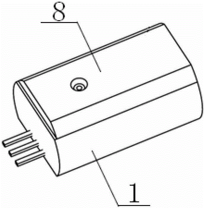
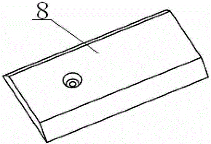
[0083] The modular sensor provided by the present invention is mainly used for active sensors, such as figure 2 , image 3 and Figure 4 As shown, it includes a cavity module 1 , a skeleton module 2 , a circuit board, a Hall chip 4 and a cover plate 8 , wherein the circuit board takes a flexible circuit board 3 as an example.

[0084] Such as Figure 5 As shown, the cavity module 1 is a shell with an open top. There is a positioning groove 12 in the middle of the bottom of the shell. The left and right sides of the positioning groove 12 are polished; the bottom of the shell is integrally molded with a PIN needle assembly 11 (eg Figure 11 shown), the PIN needle assembly 11 has three obtuse-angled PIN needles 111, 112, 113, one end of which protrudes from one side of the cavity module 1, and the other end protrudes obliquely upwar...


PUM


Abstract

The invention discloses a modular sensor and a manufacturing technique thereof. The modular sensor comprises a cavity module, a framework module, a circuit board, a Hall chip and a cover plate, the top of the cavity module is opened, a positioning groove is formed in the bottom of the cavity module, and the cavity is integrally injected and molded with PIN needle module; strip through holes are formed in the rear end of the framework module, two position spacing tables are arranged on the upper end surface of the framework module, a positioning lug boss is arranged on the lower end surface of the framework module, and a clamp groove comprising two buckles and one support table and used for accommodating the hall chip is formed in the outer part of the front end of the framework module. The buckle adopts an inner side interference pointed hook part and an end surface hot riveting spur, so as to enable the hall chip to be fixed and confined in the space; the elasticity of the metal PIN needle and the matching structure of the cavity module and the framework module guarantee the framework module to be accurately positioned and fixedly connected in the cavity body module, and prevent the electric element from being damaged after glue flowing uncontrolled cover the electronic element temperature shock; the front end surface of the hall chip and the front cavity surface of the cavity module are closely pressed, but the compression force is not so large as to cause deformation and damage of the cavity module front end, so as to effectively guarantee sensor information.

Description

technical field [0001] The invention relates to sensor technology, in particular to a modular active sensor and its manufacturing process. The sensor can be used in automobile engines, gearboxes and ABS anti-lock braking systems. Background technique [0002] At present, the speed sensor and phase sensor in the automobile engine, the speed sensor in the gearbox, and the wheel speed sensor in the ABS anti-lock braking system include passive and active types, of which passive sensors are called passive sensors. Active sensors are called active sensors. Compared with passive sensors, active sensors have the advantages of small size, light weight, high integration, fast response, and strong anti-interference ability, so they are more and more widely used. [0003] There are mainly two molding methods for existing active sensors, which are integral injection molding and bracket shell assembly. [0004] The integral injection molding type is to connect the integrated circuit ele...

Claims


Application Information

Patent Timeline
Patent Type & Authority Applications(China)
IPC IPC(8): G01P1/00G01P3/44
Inventor 何元飞
Owner UNITED AUTOMOTIVE ELECTRONICS SYST
Learn More