Anti-gravity loop heat pipe and production method thereof

A technology of loop heat pipe and manufacturing method, applied in the direction of sustainable manufacturing/processing, indirect heat exchanger, lighting and heating equipment, etc., which can solve the problems of large temperature fluctuation, reduced heat transfer capacity, and limited heat transfer performance, etc. Achieve the effects of small temperature fluctuations, stable reflux speed, and improved heat transfer efficiency

Inactive Publication Date: 2013-09-25
SOUTH CHINA UNIV OF TECH
View PDF6 Cites 15 Cited by
  • Summary
  • Abstract
  • Description
  • Claims
  • Application Information

AI Technical Summary

Problems solved by technology

However, for the traditional loop heat pipe radiator, the distribution of temperature is changed according to the location of the heat source, when the distance from the heat source increases, so the traditional loop heat pipe radiator has poor heat transfer efficiency due to the loop heat pipe, resulting in low cooling efficiency
At the same time, as the distance increases, the heat transfer performance of the traditional loop heat pipe is also greatly limited. The return velocity of the working medium is unstable, the temperature fluctuates greatly, and it is difficult to ensure that the temperature control is within the specified working range.
Especially under anti-gravity conditions, the heat transfer capacity is greatly reduced, and even low power failures may occur
Under anti-gravity conditions, due to the influence of gravity, the burden of the return flow of the working medium of the loop heat pipe is greatly increased, resulting in unstable return flow of the working medium
The unstable circulation velocity of the working medium will lead to fluctuations in the temperature of the heat source, especially when the heat sink is far away from the heat source or the temperature of the heat source is not working under the target load of the loop heat pipe design, it will inevitably lead to severe fluctuations in the temperature of the heat source

Method used


Image

  • Anti-gravity loop heat pipe and production method thereof
  • Anti-gravity loop heat pipe and production method thereof
  • Anti-gravity loop heat pipe and production method thereof

Examples


Embodiment 1

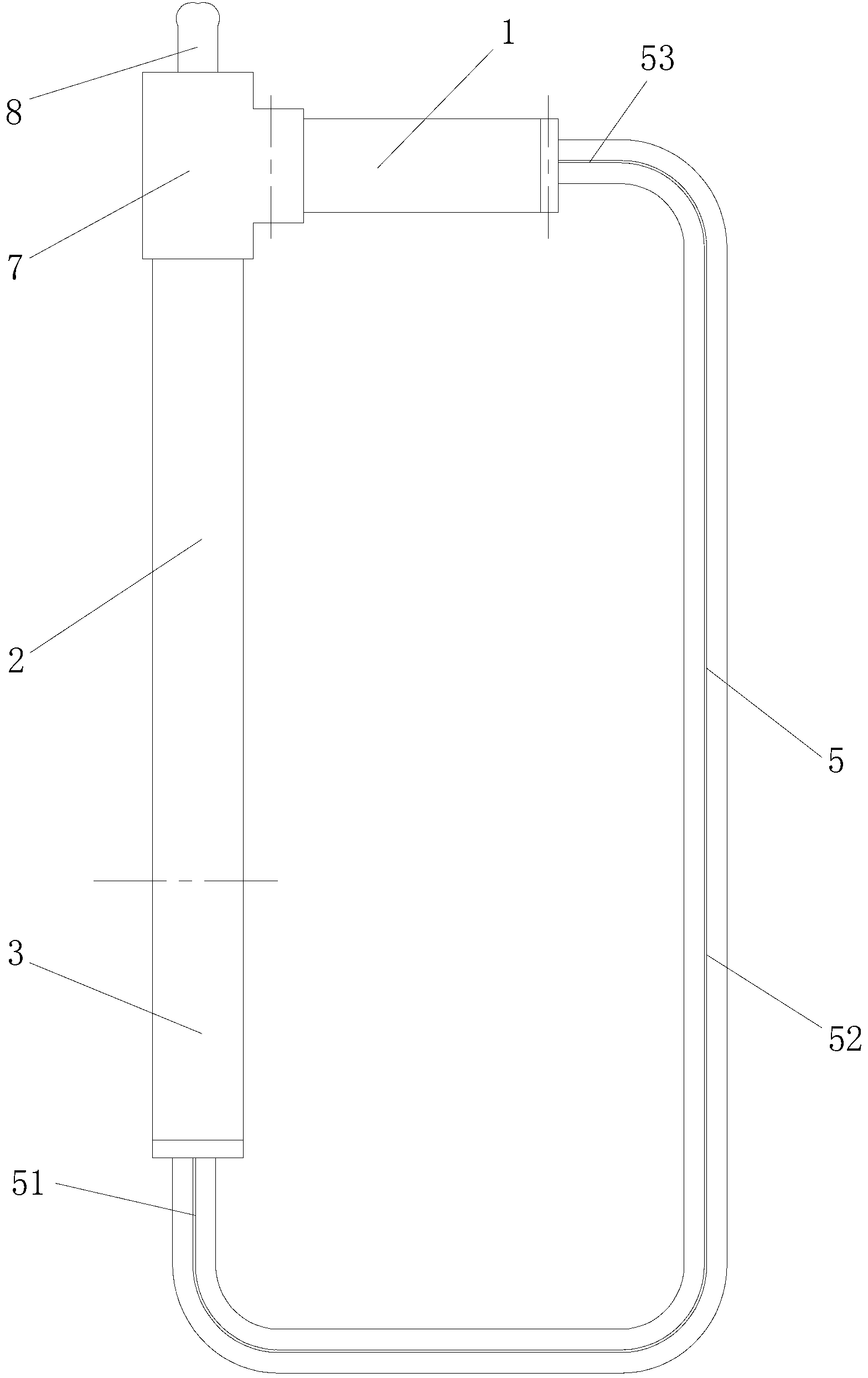
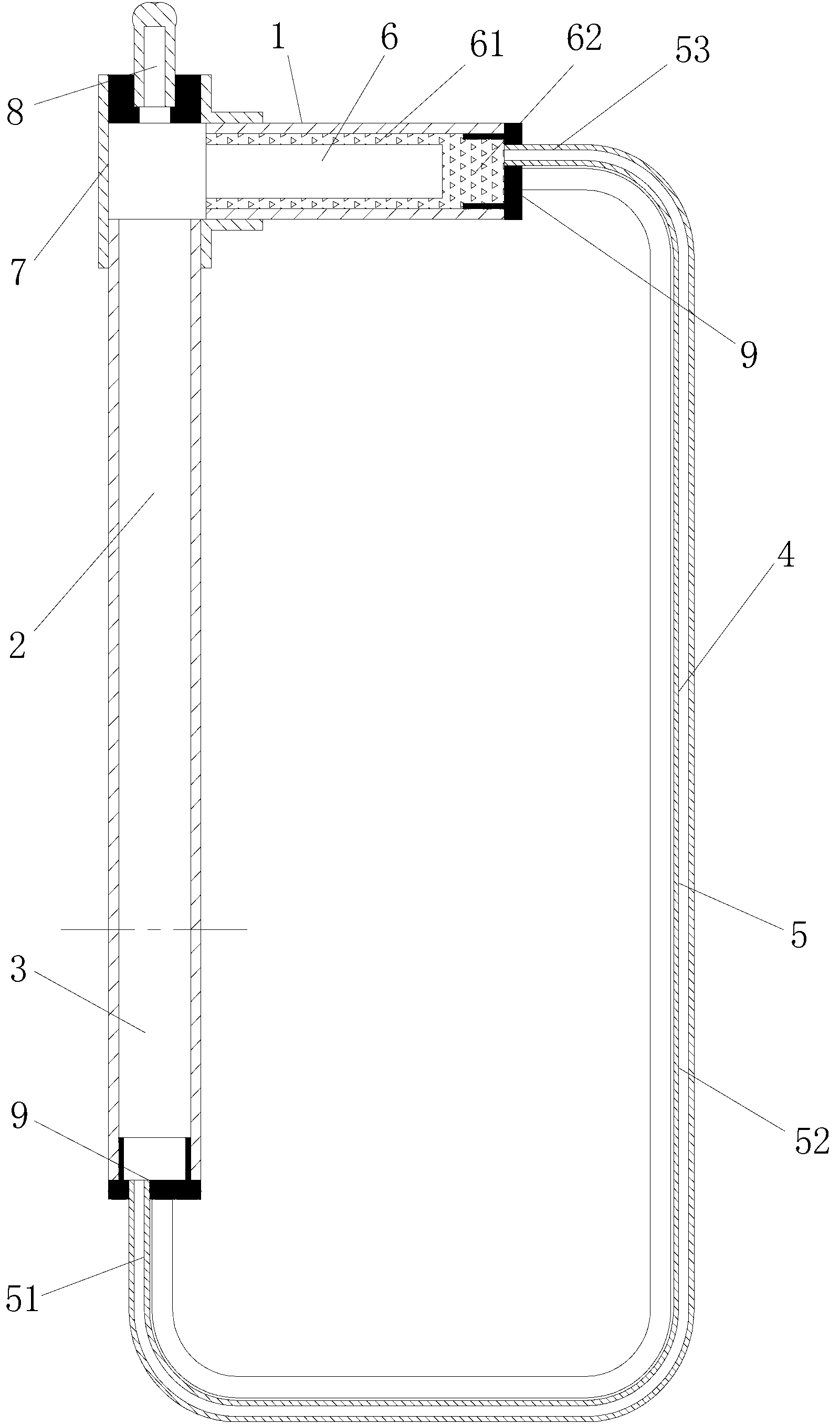
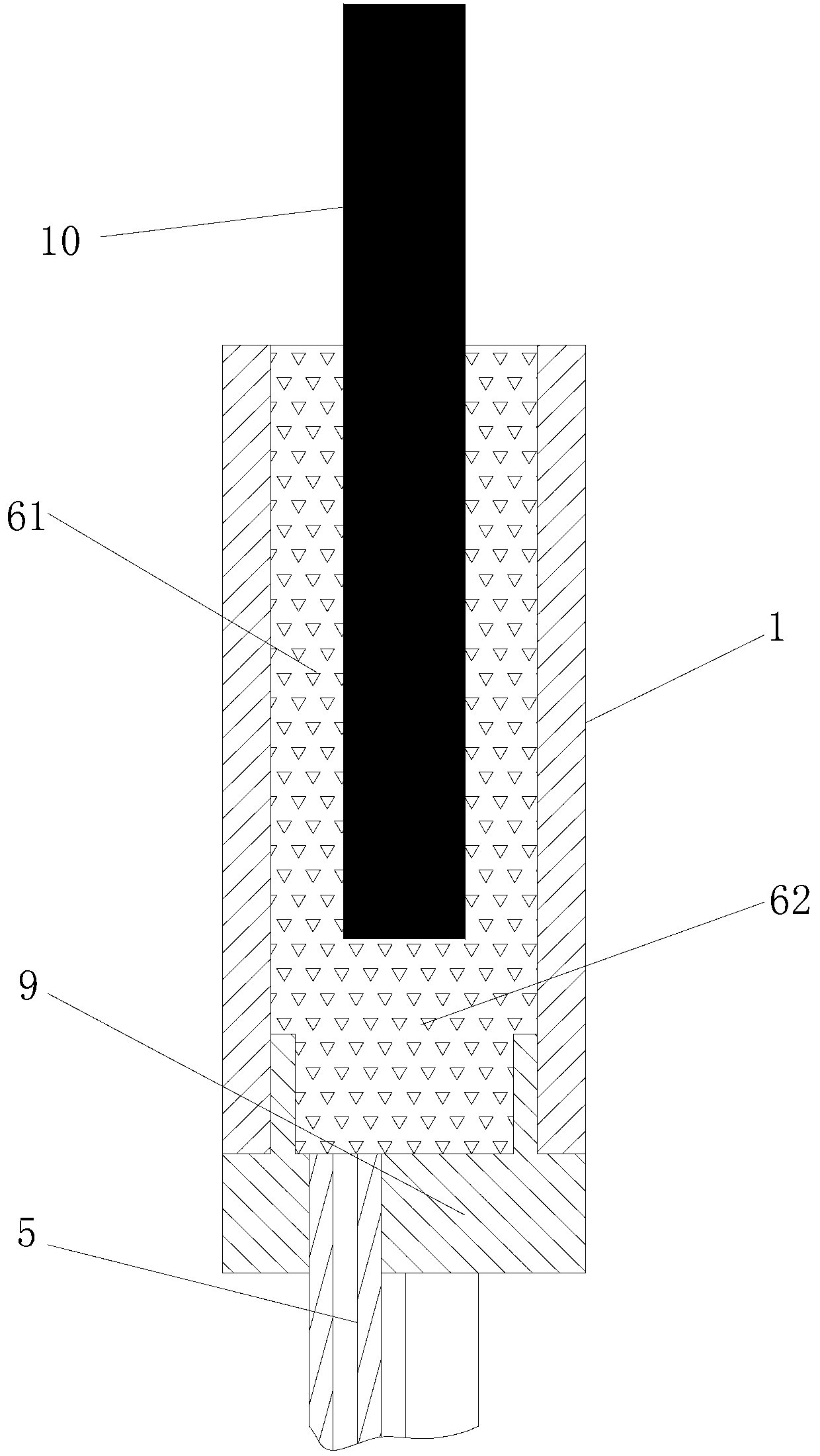
[0028] Such as figure 1 and figure 2 The anti-gravity loop heat pipe shown has an evaporation section 1, an adiabatic section 2, a condensation section 3, and an infusion section 4 that are sequentially connected end to end to form a loop. The infusion section 4 includes three capillary tubes 5, and the capillary tube 5 The two ends of the capillary are respectively connected with the evaporating section 1 and the condensing section 3; the inner diameters of the capillary 5 are smaller than the inner diameters of the tube bodies of the evaporating section 1 and the condensing section 3; The outlet end of the evaporation section 1 and the inlet end of the heat insulation section 2 are connected through the three-way adapter 7, that is, the outlet end of the evaporation section 1 and the inlet end of the heat insulation section 2 are respectively connected to the two interfaces of the three-way adapter 7 , and the third interface of the three-way adapter 7 is provided with a s...

Embodiment 2

[0043] The anti-gravity loop heat pipe is the same as the embodiment 1 except the following technical features: the number of the capillary 5 is two. The diameter of the inner hole of the capillary 5 is 0.5 mm.


PUM

PropertyMeasurementUnit
Thicknessaaaaaaaaaa
Outer diameteraaaaaaaaaa

Abstract

The invention discloses an anti-gravity loop heat pipe. The anti-gravity loop heat pipe comprises an evaporation segment, an insulating segment, a condensation segment and a liquid conveying segment, which are connected end to end to form a loop. The liquid conveying segment comprises at least one capillary tube, and two ends of every capillary tube are connected with the evaporation segment and the condensation segment respectively; the inner diameter of the capillary tubes is smaller than that of the pipe body of the evaporation segment and the pipe body of the condensation segment; a liquid-absorbing core passage is formed in the evaporation segment. The anti-gravity loop heat pipe drives liquid working medium to quickly move in the pipe by capillary force, has fine return speed stability and higher heat transfer efficiency, and is applicable to the complex fields having high radiating condition requirements, such as aerospace, photoelectrons, chemical industry and power engineering. The invention further provides a production method of the anti-gravity loop heat pipe.

Description

technical field [0001] The invention relates to heat transfer equipment technology, in particular to an anti-gravity loop heat pipe and a manufacturing method thereof. Background technique [0002] Thermal control has always been a key consideration in the design of electronic instrument components, because electronic instruments operate better within a certain temperature range. However, with the advancement of industrial design densification and miniaturization, the trend of smallest functional devices, stronger functions, and faster processors has led to a constant increase in the heat dissipation per unit area of ​​the system, especially with increasingly dense high-heat flux components. The multi-chip module was born. This means that various thermal resistances from the internal heat source to the external heat sink must be reduced, and new requirements are placed on heat transfer and heat dissipation technologies. [0003] The traditional loop heat pipe radiator show...

Claims


Application Information

Patent Timeline
IPC IPC(8): F28D15/04
CPCY02P20/10
Inventor 李炳林李辉汤勇周蕤陆龙生
Owner SOUTH CHINA UNIV OF TECH
Why Eureka
Try Eureka