Light-emitting diode (LED) bulb lamp

A technology for LED bulbs and lamp caps, which is applied to the cooling/heating device, lighting device, light source and other directions of lighting devices, can solve problems such as unfavorable heat dissipation, insufficient understanding of heat dissipation mechanism, and reduced heat dissipation efficiency of light source modules, so as to improve the heat dissipation effect. , Improve heat dissipation efficiency and increase the effect of heat dissipation area

Inactive Publication Date: 2013-09-25
GUANGDONG ECORISING TECH
View PDF7 Cites 6 Cited by
  • Summary
  • Abstract
  • Description
  • Claims
  • Application Information

AI Technical Summary

Problems solved by technology

The technical solution described in this patent has many unreasonable points. First, the heat generated by the power module is quite large, even no less than the heat generated by the light source module. In order to maintain the life of the light source module, the power module and the light source module should not be used Share a heat dissipation system, because this will greatly reduce the heat dissipation efficiency of the light source module. In the current technical level, R&D personnel generally cannot understand the powerful principles, and always try to improve the function of the heat sink, so that the heat sink can be used at the same time. Focusing on heat dissipation in other aspects, instead of focusing on the heat dissipation of the light source module; secondly, excessive heat convection, as a result, the hot air flows out of the lamp after several twists and turns in the lamp cavity, which is actually not conducive to heat dissipation. This is also the reason why people in the field do not know enough about the heat dissipation mechanism.

Method used


Image

  • Light-emitting diode (LED) bulb lamp
  • Light-emitting diode (LED) bulb lamp
  • Light-emitting diode (LED) bulb lamp

Examples


Embodiment Construction

[0043] The specific embodiments of the present invention will be further described below in conjunction with the accompanying drawings.

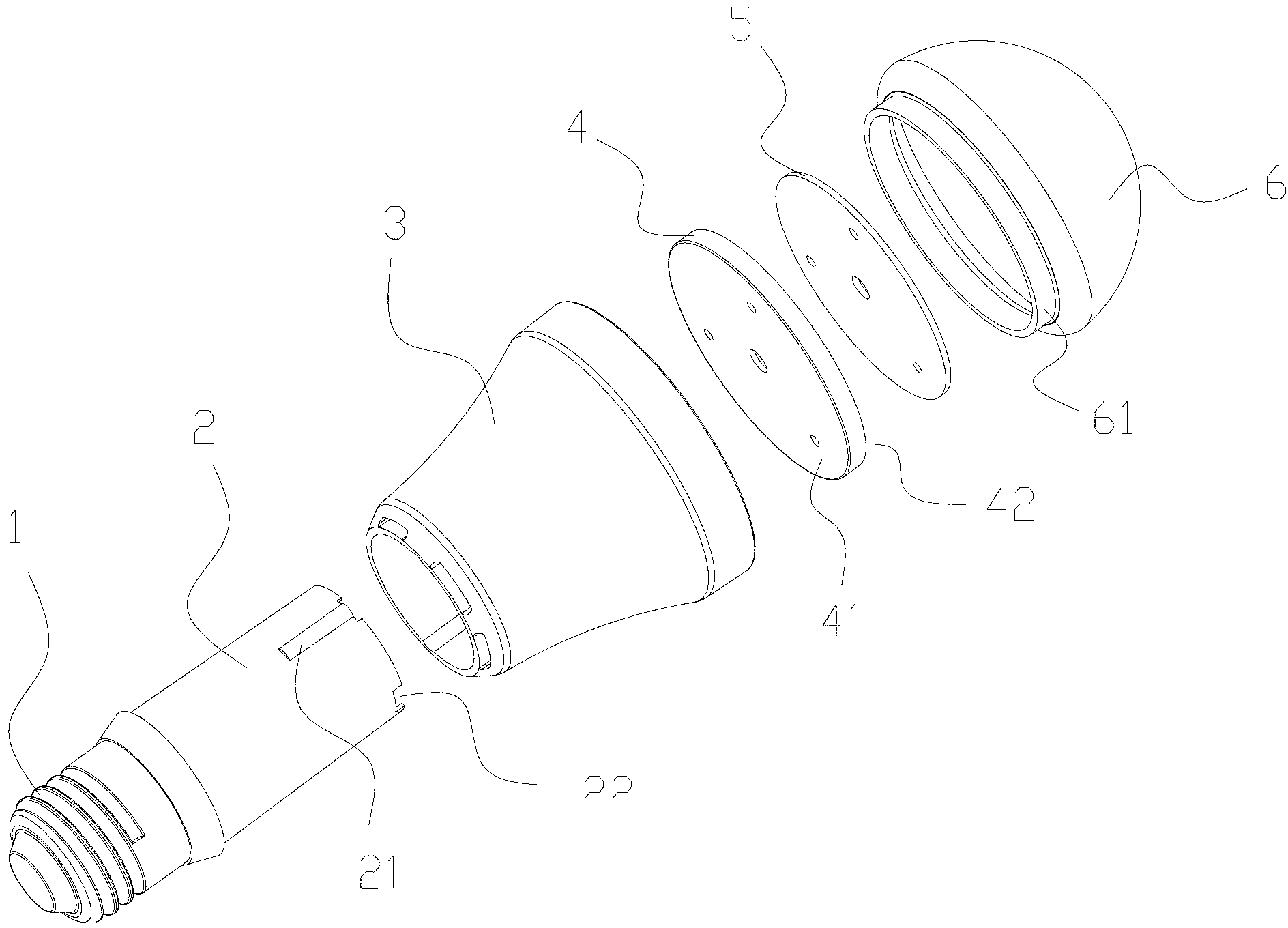
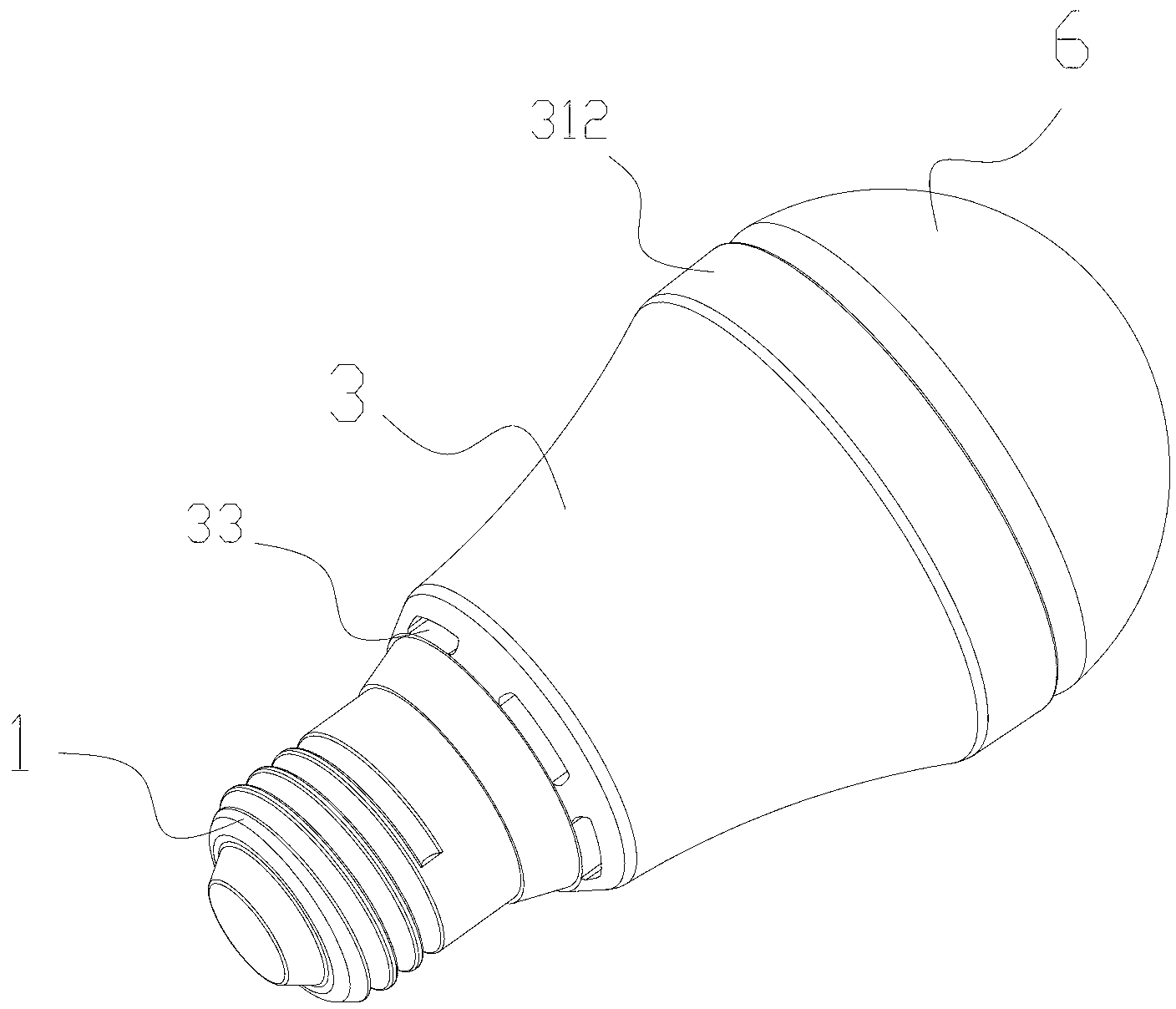
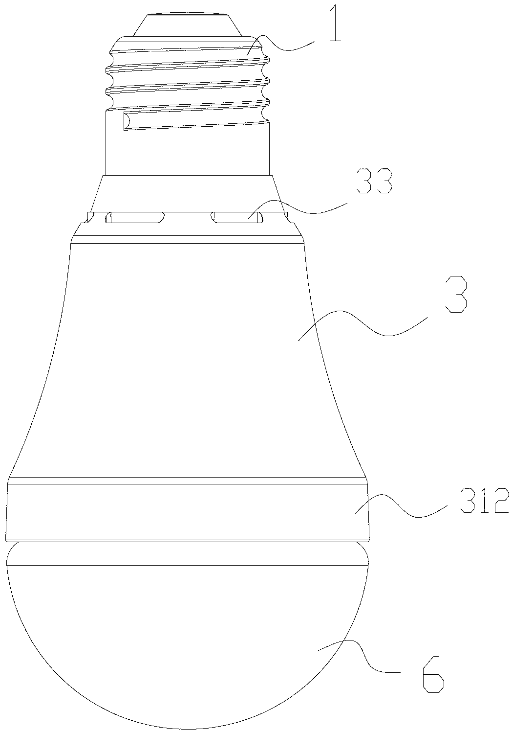
[0044] Such as Figure 1 to Figure 6 As shown, a schematic structural diagram of an LED bulb lamp in this embodiment, which includes a lamp base 1 , an inner container 2 , a power module, a heat dissipation lamp cup 3 , a heat dissipation substrate 4 , an LED light emitting board 5 and a lampshade 6 .

[0045] The lamp cap 1 is used to connect with the lamp socket connected to the mains, low-voltage electricity and other power sources. One end of it used to connect the lamp socket is a metal conductive and heat-conducting screw structure. The type of lamp head is the same, which is used to easily replace the traditional bulb lamp without additional replacement lamp holder. The other end of the lamp holder 1 is connected with the inner container 2 .

[0046] The liner 2 is made of insulating, heat-insulating, and heat-resistant materials, a...


PUM


Abstract

The invention discloses an LED bulb lamp. The LED bulb lamp comprises a lamp holder, a liner, a power module, a cooling lamp cup, a cooling substrate, an LED light-emitting plate and a lamp shade which are connected in a matched mode, wherein the lamp holder is arranged at the upper end of the liner, the liner is made of a heat-insulating material, the power module is arranged inside the liner, the liner is filled with a heat-conducting material, the cooling lamp cup comprises an inner casing and an outer casing, a cavity is formed in the center of the inner casing, the liner is arranged inside the cavity, an annular band gap space is formed between the inner casing and the outer casing and separated into a plurality of ventilating ducts which are through in an up-and-down mode, a plurality of cooling fins which are connected with the inner casing and the outer casing are arranged inside the band gap space, the band gap space is separated by the cooling fins to form the ventilating ducts, a bottom plate is arranged at the lower end of the inner casing, and the cooling substrate, the LED light-emitting plate and the lamp shade are installed on the bottom plate sequentially. According to the LED bulb lamp, the good cooling effect is achieved through the method that separated cooling of a power supply and a light-emitting portion is performed.

Description

technical field [0001] The invention relates to the field of LED lighting, in particular to an LED bulb lamp. Background technique [0002] LED light source is recognized as the most promising lighting source in the 21st century. Its advantages such as green environmental protection, long life, energy saving, high reliability, good light efficiency and small size make LED light source more energy-saving than traditional incandescent lamps and fluorescent lamps. Lamps, etc. have greater application prospects. [0003] With the development of LED technology, the high luminous efficiency, ultra-high brightness and full color of LED continue to develop and innovate, and its technical requirements for lamp design and application are getting higher and higher. How to improve the structure of lamps, prolong the life of lamps, increase the level of energy saving, solve heat dissipation problems, optimize optical design, and save production costs, etc., are the areas that the indust...

Claims


Application Information

Patent Timeline
Patent Type & Authority Applications(China)
IPC IPC(8): F21V29/00F21Y101/02F21V29/50F21V29/75
Inventor 钟群
Owner GUANGDONG ECORISING TECH
Why Eureka
Try Eureka