Labyrinth seal, cleaning unit and method, and solution film-forming method

A technology of labyrinth sealing and cleaning objects, applied in the field of cleaning units and labyrinth seals, can solve the problems of dry ice leakage, adhesion, weak attraction, etc., to prevent the external size from increasing, inhibit the external size from increasing, and achieve high sealing effect of effect

Inactive Publication Date: 2013-09-18
FUJIFILM CORP
View PDF6 Cites 4 Cited by
  • Summary
  • Abstract
  • Description
  • Claims
  • Application Information

AI Technical Summary

Problems solved by technology

However, the method of Japanese Patent Publication No. 2009-078444 has the following problems: in the process of continuing to cast and peel off, dry ice particles or gaseous carbon dioxide are attached and solidified on the labyrinth seal, and the solidified dry ice moves towards the labyrinth seal. External leakage of components and chambers
However, the attraction force is weak, so there is still a problem that dry ice particles or gaseous carbon dioxide adhere to the labyrinth seal and fly out to the outside

Method used


Image

  • Labyrinth seal, cleaning unit and method, and solution film-forming method
  • Labyrinth seal, cleaning unit and method, and solution film-forming method
  • Labyrinth seal, cleaning unit and method, and solution film-forming method

Examples


Embodiment 1

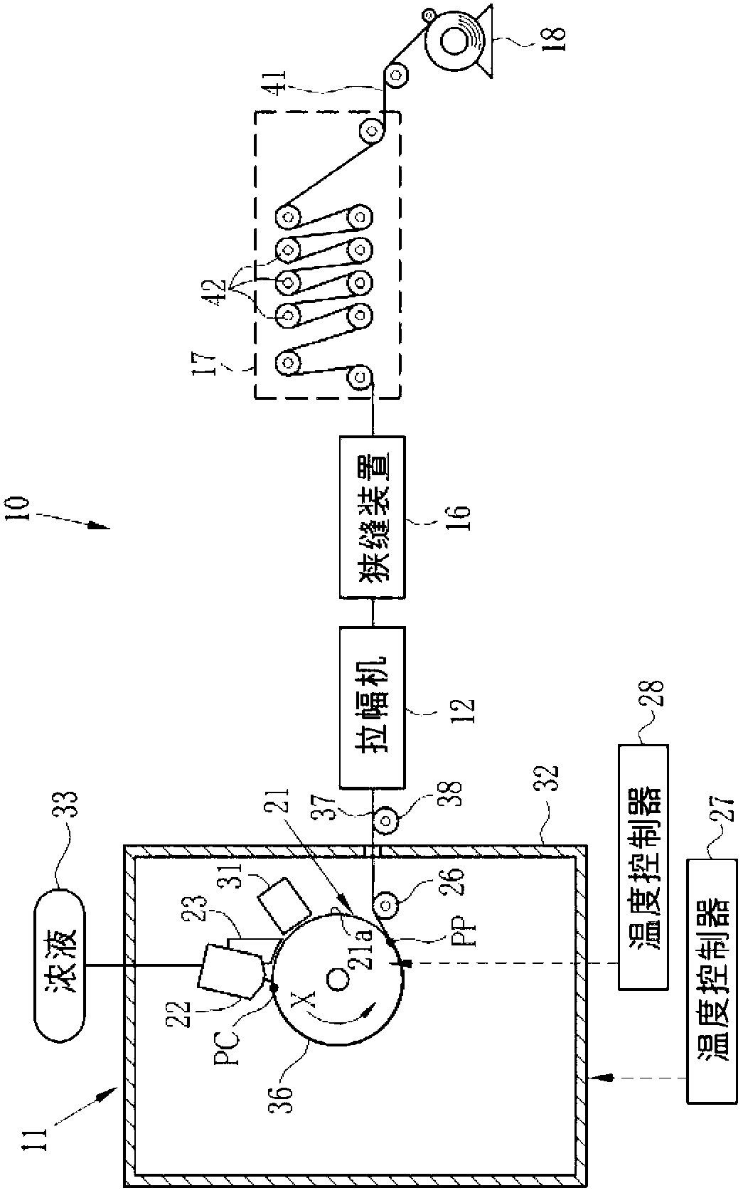
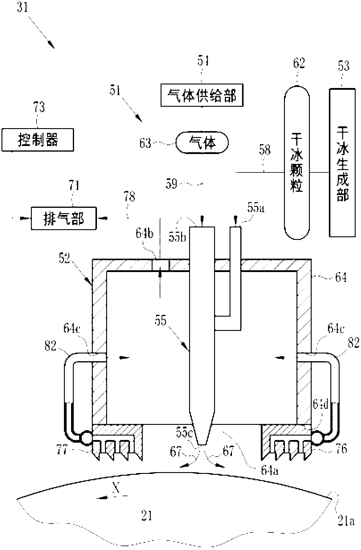
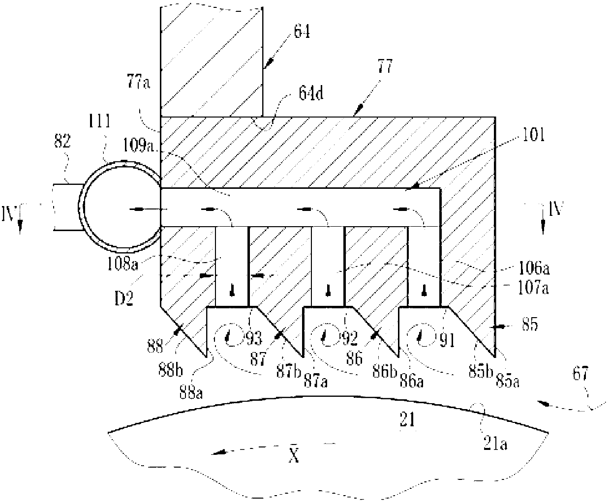
[0097] The thin film 41 is produced by the solution film forming apparatus 10 . The respective diameters D2 of the second passages 106a to 106d, 107a to 107d, and 108a to 108d of the labyrinth seal 77 are equal to each other, and are shown in the "D2" column of Table 1 (unit: mm). In addition, the pitch L1 of the second passing paths 108a to 108d of the groove 93, the pitch L1 of the second passing paths 107a to 107d of the groove 92, and the pitch L1 of the second passing paths 106a to 106d of the groove 91 are equal to each other, as shown in Table 1. "L1" column (unit: mm). In addition, the column of "Number of Second Passages" in Table 1 describes the number of second passages branched from one first passage. For example, three second passages 106a, 107a, and 108a are formed by branching from the first passage 109a, so it is "3". Since the 1st passing path 109a, the 1st passing path 109b, the 1st passing path 109c, and the 1st passing path 109d have the same structure, i...

Embodiment 2

[0102] A labyrinth formula is used in which the distance L1 of the second passages 108a to 108d, the distance L1 of the second passages 107a to 107d, and the distance L1 of the second passages 106a to 106d are the values ​​shown in the "L1" column of Table 1. Seals 76,77. And the tube 82 connected to each manifold 111 is set as one. Conditions other than these were the same as in Example 1.

[0103] In the same manner as in Example 1, it was evaluated whether contamination, solidified dry ice, or the like leaked to the outside from between the labyrinth seals 76, 77 and the peripheral surface 21a. The evaluation results are shown in Table 1.

Embodiment 3

[0105] A labyrinth formula is used in which the distance L1 of the second passages 108a to 108d, the distance L1 of the second passages 107a to 107d, and the distance L1 of the second passages 106a to 106d are the values ​​shown in the "L1" column of Table 1. Seals 76,77. And the tube 82 connected to each manifold 111 is set as one. Conditions other than these were the same as in Example 1.

[0106]In the same manner as in Example 1, it was evaluated whether contamination, solidified dry ice, or the like leaked to the outside from between the labyrinth seals 76, 77 and the peripheral surface 21a. The evaluation results are shown in Table 1.


PUM


Abstract

The invention provides a labyrinth seal, a cleaning unit and a method, and a solution film-forming method. The cleaning unit comprises cleaning gas (67) containing dry ice particles, which can be injected by a nozzle and can be contacted with a periphery (21a). A cleaning area of the periphery (21a) contacted with the cleaning gas (67) is covered by a housing main body (64) to attract the gas in the housing main body (64), and therefore the pollutant peeled from the periphery (21a) or the cleaning gas (67) can be attracted. An opposite surface (64d) opposite to the periphery (21a) of the housing main body (64) is provided with the labyrinth seal (77), which is provided with a hole (101) provided openings toward grooves (91-93) and a wall surface (77a) of the nozzle side to penetrate the inner side. The holes (101) are connected with a gas exhaust part (71) by a collecting pipe (111) and a pipe (82). The gas exhaust part (71) can be used to attract the gas around lugs (82-88).

Description

technical field [0001] The invention relates to a labyrinth seal, a cleaning unit and method, and a method for forming a film from a solution. Background technique [0002] There is dry ice blasting as a method for cleaning parts whose surfaces are contaminated. Dry ice blasting is a cleaning method that sprays solid dry ice particles (dry ice snow) on the surface of the object to be cleaned with pollutants attached, and removes pollutants from the surface of the object to be cleaned by collision and sublimation of the dry ice particles. [0003] During dry ice blasting, the dry ice particles ejected from the cleaning machine or the dry ice particles and gas carbon dioxide that bounce off the surface of the object to be cleaned, and the pollutants stripped from the object to be cleaned are likely to fly around the object to be cleaned or the cleaning machine. [0004] On the other hand, there is a solution film-forming method as a method for producing a thin film. The solu...

Claims


Application Information

Patent Timeline
Patent Type & Authority Applications(China)
IPC IPC(8): F16J15/447B08B7/00B29D7/01C08J5/18
CPCB29C43/46
Inventor 尾堂太亮长谷川昌孝铃木信行横山和正
Owner FUJIFILM CORP
Why Eureka
Try Eureka