labyrinth seal

A technology of labyrinth sealing and sealing fins, applied in the field of cleaning units and labyrinth seals, can solve the problems of dry ice leakage, adhesion, weak attraction, etc. The effect of the sealing effect

Inactive Publication Date: 2017-05-10
FUJIFILM CORP
View PDF2 Cites 0 Cited by
  • Summary
  • Abstract
  • Description
  • Claims
  • Application Information

AI Technical Summary

Problems solved by technology

However, the method of Japanese Patent Publication No. 2009-078444 has the following problems: in the process of continuing to cast and peel off, dry ice particles or gaseous carbon dioxide are attached and solidified on the labyrinth seal, and the solidified dry ice moves towards the labyrinth seal. External leakage of components and chambers
However, the attraction force is weak, so there is still a problem that dry ice particles or gaseous carbon dioxide adhere to the labyrinth seal and fly out to the outside

Method used


Image

  • labyrinth seal
  • labyrinth seal
  • labyrinth seal

Examples


Embodiment 1

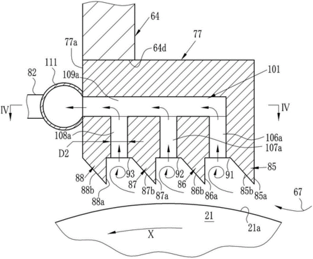
[0097] The thin film 41 is manufactured by the solution film forming apparatus 10. The diameters D2 of the second passages 106a to 106d, 107a to 107d, and 108a to 108d of the labyrinth seal 77 are equal to each other, and are shown in the "D2" column of Table 1 (unit: mm). In addition, the pitch L1 of the second passages 108a to 108d of the groove 93, the pitch L1 of the second passages 107a to 107d of the groove 92, and the pitch L1 of the second passages 106a to 106d of the groove 91 are equal to each other, as shown in Table 1. "L1" column (unit: mm). In addition, in the "Number of Second Passing Roads" column in Table 1, the number of second passing roads branched from one first passing road is described. For example, it is "3" because it branches from the first passage 109a to form three second passages 106a, 107a, and 108a. Since the first passage 109a, the first passage 109b, the first passage 109c, and the first passage 109d have the same structure, they become "3". ...

Embodiment 2

[0102] A labyrinth type in which the distance L1 of the second passages 108a to 108d, the distance L1 of the second passages 107a to 107d, and the distance L1 of the second passages 106a to 106d are set to the values ​​shown in the "L1" column of Table 1 is used Seals 76,77. And the pipe 82 connected to each manifold 111 is set to one. The conditions other than these are the same as in Example 1.

[0103] In the same method as in Example 1, it was evaluated whether contaminants, solidified dry ice, etc. leaked from between the labyrinth seals 76, 77 and the peripheral surface 21a to the outside. The evaluation results are shown in Table 1.

Embodiment 3

[0105] A labyrinth type in which the distance L1 of the second passages 108a to 108d, the distance L1 of the second passages 107a to 107d, and the distance L1 of the second passages 106a to 106d are set to the values ​​shown in the "L1" column of Table 1 is used Seals 76,77. And the pipe 82 connected to each manifold 111 is set to one. The conditions other than these are the same as in Example 1.

[0106] In the same method as in Example 1, it was evaluated whether contaminants, solidified dry ice, etc. leaked from between the labyrinth seals 76, 77 and the peripheral surface 21a to the outside. The evaluation results are shown in Table 1.


PUM


Abstract

PROBLEM TO BE SOLVED: To suppress scattering of solidified dry ice to the outside of a labyrinth seal and a change in an external size of the labyrinth seal.SOLUTION: A cleaning unit discharges cleaning gas 67 containing dry ice particles from a nozzle and impinges the cleaning gas to a circumferential surface 21a. A cleaning area on the circumferential surface 21a to which the cleaning gas 67 is impinged is covered with a casing body 64, the gas within the casing body 64 is sucked and, thereby, contaminant coming off from the circumferential surface 21a, the cleaning gas 67, etc. are sucked. A labyrinth seal 77 is disposed on an opposite surface 64d opposite to the circumferential surface 21a of the casing body 64, and the labyrinth seal 77 has a hole 101 which is opened to each of grooves 91 to 93 and a wall surface 77a of the nozzle side and penetrates the insides. The hole 101 is connected with a second exhaust part by means of a collecting pipe 111 and a pipe 82. Gas on the surrounding of fins 85 to 88 is sucked by a second exhaust part.

Description

Technical field [0001] The invention relates to a labyrinth seal, a cleaning unit and method, and a solution film forming method. Background technique [0002] As a method of cleaning contaminated parts on the surface, there is dry ice cleaning. Dry ice cleaning is a cleaning method in which solid dry ice particles (dry ice and snow) are sprayed onto the surface of an object to be cleaned with contaminants, and the contaminants are removed from the surface of the object by collision and sublimation of the dry ice particles. [0003] In dry ice cleaning, dry ice particles ejected from a washing machine, dry ice particles and gaseous carbon dioxide that bounce back when hitting the surface of the object to be cleaned, and contaminants stripped from the object to be cleaned are easily scattered around the object to be cleaned or the cleaning machine. [0004] On the other hand, as a method of manufacturing a thin film, there is a solution film method. The solution film forming method,...

Claims


Application Information

Patent Timeline
Patent Type & Authority Patents(China)
IPC IPC(8): F16J15/447B08B7/00B29D7/01C08J5/18
CPCB29C43/46
Inventor 尾堂太亮长谷川昌孝铃木信行横山和正
Owner FUJIFILM CORP
Why Eureka
Try Eureka