
Movable water retaining dam for water conservancy landscape

A technology of movable retaining and movable dams, which is applied in water conservancy projects, sea area engineering, coastline protection, etc. It can solve the problems of slow lifting speed of the dam body, long construction period, poor impact resistance, etc., and achieve strong anti-flood impact and fast dam drop , the effect of a reasonable structure

Inactive Publication Date: 2013-09-18
陕西鼎航建设工程有限公司
View PDF6 Cites 33 Cited by
  • Summary
  • Abstract
  • Description
  • Claims
  • Application Information

AI Technical Summary

Problems solved by technology

Commonly used dams include rubber dams, sluice gates and flap gate dams. Rubber dams are widely used because they are close to the river bed without blocking water, simple in structure, large in span, good in seismic performance, beautiful in shape, and light in weight. , the rubber dam is made of rubber material, which has poor impact resistance, is easy to be scratched by sharp objects, the dam body is easy to burst, and the dam body lifting speed is too slow; although the sluice gate is strong and durable, its construction period is long and the cost is high; the flap door Although the structure of the dam is simple and the construction period is short, it cannot withstand the impact of severe floods, causing it to fail to automatically flap and affect flood control safety. Normal water storage makes it impossible to clean up the floating objects, making the river channel dirty and affecting the landscape effect

Method used


Image

  • Movable water retaining dam for water conservancy landscape
  • Movable water retaining dam for water conservancy landscape
  • Movable water retaining dam for water conservancy landscape

Examples


Embodiment Construction

[0021] The present invention will be further described below in combination with specific embodiments.

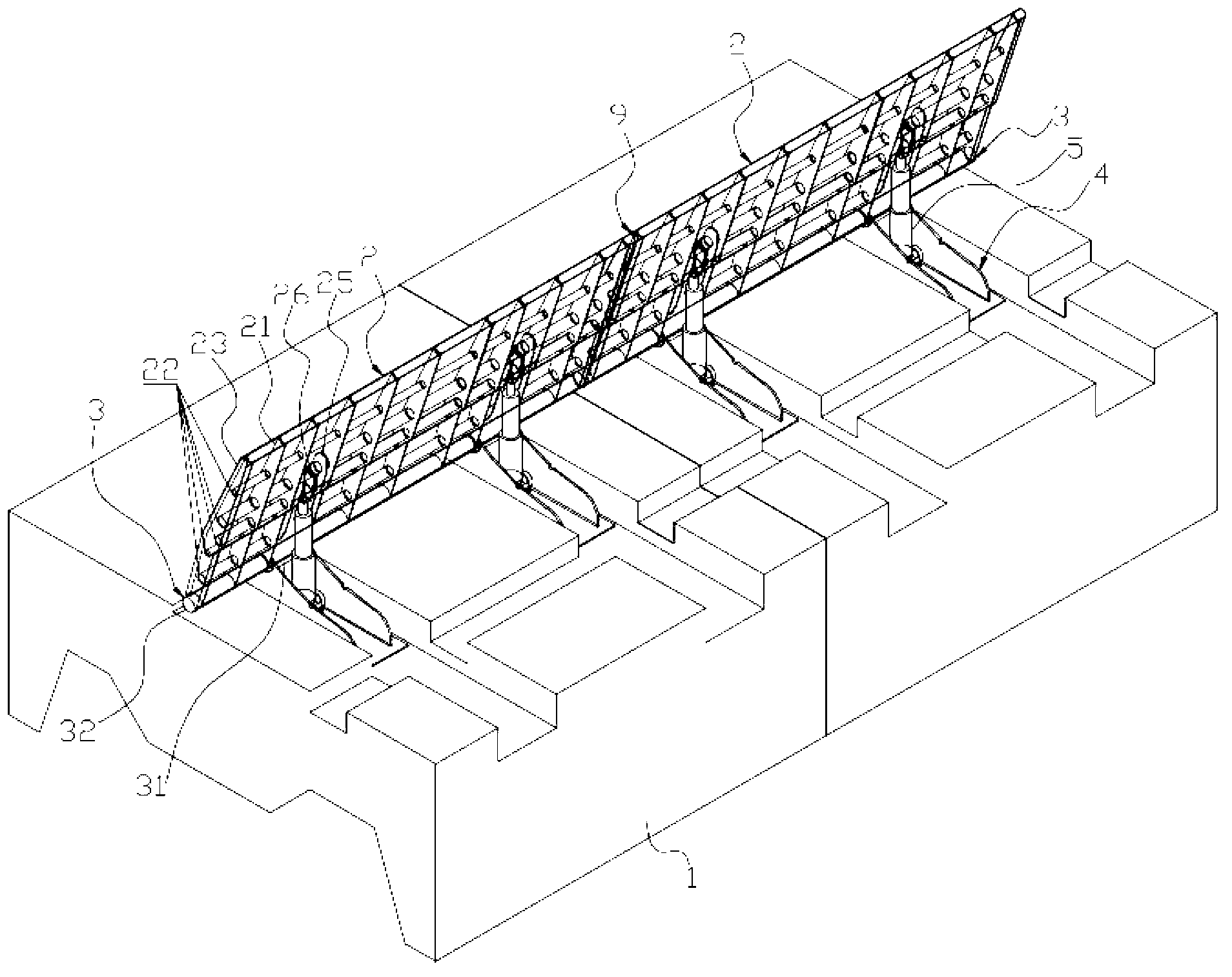
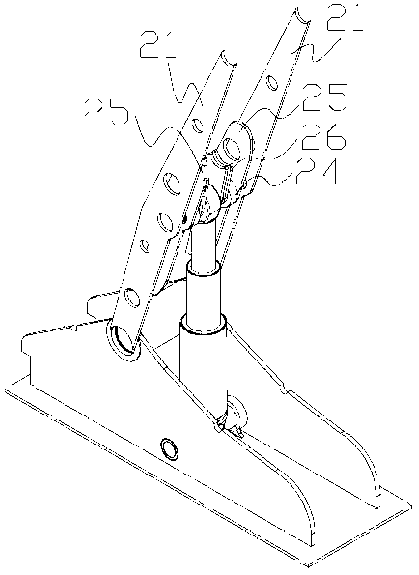
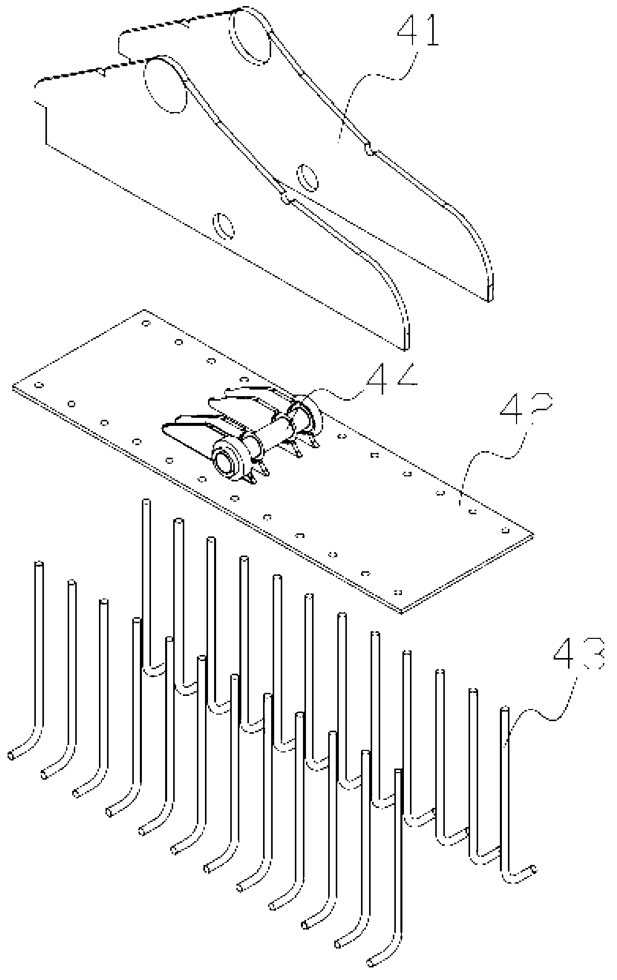
[0022] Such as Figures 1 to 6 As shown, the water conservancy landscape movable retaining dam according to an embodiment of the present invention includes a dam foundation 1, a movable dam surface 2, a bottom rotating shaft 3, a foundation embedded fixing seat 4, a hydraulic cylinder 5, a hydraulic pump station 6 and a water retaining height control device7. The foundation embedded fixing seat 4 is inlaid and installed on the dam foundation 1 by pouring. The bottom rotating shaft 3 includes a shaft sleeve 31 and a shaft core 32. The shaft sleeve 31 is fixedly connected to the foundation embedded fixing seat 4 by welding, and the shaft core 32 passes Set on the shaft sleeve 31, the shaft core 32 is welded and fixedly connected to the movable dam surface 2. According to the principle of triangular mechanics, the movable dam surface 2 can rotate around the shaft core 32, and...


PUM


Abstract

The invention discloses a movable water retaining dam for a water conservancy landscape. The movable water retaining dam comprises a dam foundation, movable dam faces, bottom rotating shafts, foundation embedded fixing seats, hydraulic cylinders, hydraulic pump stations and water retaining height control devices, wherein the foundation embedded fixing seats are mounted on the dam foundation; the bottom rotating shafts are mounted on the foundation embedded fixing seats; the movable dam faces are fixedly connected to the bottom rotating shafts; the movable dam faces can rotate around the bottom rotating shafts; one end of each hydraulic cylinder is movably connected with the back side of one movable dam face, and the other end of each hydraulic cylinder is movably connected with one foundation embedded fixing seat; and the hydraulic cylinders are connected with the hydraulic pump stations which are connected with the water retaining height control devices. The movable water retaining dam is reasonable in structure, firm, reliable and high in flood impact resistance, is not influenced by floating impurities, is not limited by width of a river, is not prone to retain the floating impurities, can be controlled automatically and can be ascended and descended rapidly, the dam can be descended for draining off floodwater without a battery, and flood control safety is realized.

Description

technical field [0001] The invention relates to the field of water-retaining buildings, and more particularly relates to a movable water-retaining dam for water conservancy landscapes. Background technique [0002] A dam is a water-retaining structure that intercepts the water flow of a river channel to raise the water level or regulate the flow. It is used for flood control, water supply, irrigation, hydropower generation, and improvement of shipping. Commonly used dams include rubber dams, sluice gates and flap gate dams. Rubber dams are widely used because they are close to the river bed without blocking water, simple in structure, large in span, good in seismic performance, beautiful in shape, and light in weight. , the rubber dam is made of rubber material, which has poor impact resistance, is easy to be scratched by sharp objects, the dam body is easy to burst, and the dam body lifting speed is too slow; although the sluice gate is strong and durable, its construction ...

Claims


Application Information

Patent Timeline
IPC IPC(8): E02B7/40E02B7/54E02B8/02
Inventor 王辉
Owner 陕西鼎航建设工程有限公司
Learn More