Photoelectric receiver time stability test method based on non-polarized beam splitting of dual-frequency laser

A photoelectric receiver and stability testing technology, applied in the field of laser applications, can solve problems such as inaccuracy, affecting the stability of the working time of the heterodyne interference system, and the influence of the time stability of the photoelectric receiver, to achieve accurate measurement results

Active Publication Date: 2013-09-11
HARBIN INST OF TECH
View PDF4 Cites 0 Cited by
  • Summary
  • Abstract
  • Description
  • Claims
  • Application Information

AI Technical Summary

Problems solved by technology

However, this document only theoretically analyzes the noise characteristics and data of photodetectors, and does not actually analyze the errors introduced in the electrical signal processing circuit and their impact on stability
[0005] To sum up, the current noise analysis and stability analysis of the photoelectric receiver are only realized through theory and simulation, and the time stability of the photoelectric receiver is not actually tested, so that the stability of the photoelectric receiver Calibration only stays at the stage of theoretical analysis, and it is not accurate; moreover, the current analysis only analyzes the stability of the photodetector device in the photoelectric receiver, and does not analyze the time stability of the electrical signal processing circuit of the photoelectric receiver. In practice, the electrical signal processing circuit will introduce phase drift into the output signal of the photoelectric receiver, which will affect the time stability of the photoelectric receiver, and will also affect the working time stability of the heterodyne interferometric system to a certain extent. Calibration of

Method used


Image

  • Photoelectric receiver time stability test method based on non-polarized beam splitting of dual-frequency laser

Examples


Embodiment Construction

[0020] The examples of the present invention will be described in detail below in conjunction with the accompanying drawings.

[0021] A method for testing the time stability of a photoelectric receiver based on dual-frequency laser unbiased light splitting, the steps of the method are as follows:

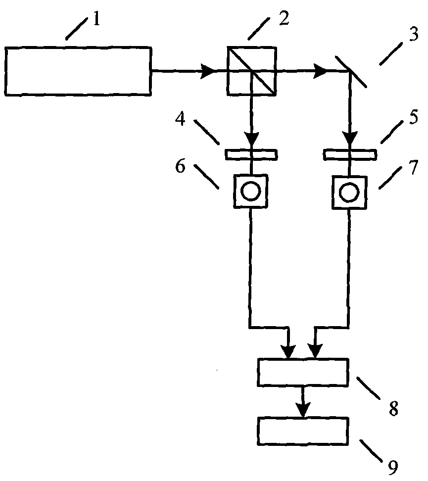
[0022] (1) Dual-frequency laser 1 emits a beam of dual-frequency laser, including 1 and v 2 , the polarization directions are mutually orthogonal linearly polarized light in the horizontal direction and the vertical direction respectively, the dual-frequency laser beam is divided into a reference beam a and a measurement beam b after passing through the unpolarized beam splitter 2, and the reference beam a and the measurement beam b both contain the frequency v 1 and frequency v 2 The orthogonal linearly polarized light;

[0023] (2) The reference beam a propagates to the analyzer a4, and the polarization direction of the analyzer a4 forms an angle of 45° with the horizontal di...


PUM


Abstract

The invention belongs to a laser application technology, and relates to a photoelectric receiver time stability test method based on non-polarized beam splitting of a dual-frequency laser. The method includes using the dual-frequency laser as a light source, utilizing a non-polarized beam splitting prism for beam splitting, and testing phase difference between a to-be-tested photoelectric receiver and a reference photoelectric receiver. The method has the advantages that in testing, linearly polarized light with the frequencies of v1 and v2 in a reference light beam is transmitted in a coaxial identical-optical-path mode, and linearly polarized light with the frequencies of v1 and v2 in a measurement light beam is transmitted in a coaxial identical-optical-path mode; phases of the two light beams are unaffected by external environmental changes, extra phase errors are not introduced, and test accuracy is high.

Description

technical field [0001] The invention belongs to laser application technology, and mainly relates to a method for testing the time stability of a photoelectric receiver based on dual-frequency laser unbiased light splitting. Background technique [0002] With its high sensitivity, high precision and non-contact characteristics, laser interferometry occupies an increasingly important position in the fields of precision and ultra-precision processing, microelectronics equipment, nanotechnology and other cutting-edge industrial equipment and national defense equipment, and has been widely used. [0003] In the laser heterodyne interferometry system, the photoelectric receiver plays an important role in realizing signal reception and signal conversion, and its performance, especially time stability, will directly affect the measurement stability and measurement accuracy of the entire measurement system. In order to study the time stability of the photoelectric receiver, Xi'an Uni...

Claims


Application Information

Patent Timeline
Patent Type & Authority Applications(China)
IPC IPC(8): G01J9/02
Inventor 谭久彬胡鹏程杨千惠
Owner HARBIN INST OF TECH
Why Eureka
Try Eureka