Eureka AIR delivers breakthrough ideas for toughest innovation challenges, trusted by R&D personnel around the world.

Semiconductor light source radiator and light source engine

A light source radiator and semiconductor technology, applied in the direction of light source, point light source, lighting and heating equipment, etc., can solve the problems of low cost of structural materials, poor heat dissipation performance of lamps and lanterns, and insufficient openings, so as to reduce material cost and material cost The effect of reduction and high manufacturing efficiency

Active Publication Date: 2013-09-11
秦彪
View PDF5 Cites 3 Cited by
  • Summary
  • Abstract
  • Description
  • Claims
  • Application Information

AI Technical Summary

Problems solved by technology

[0005]Current LED lighting uses the shell structure as a heat sink, but due to the above problems, no attention or special attention has been paid to ensuring the smooth flow of air during product design, such as : There is no convection ventilation window on the shell cover, even if there is a convection ventilation window, but the opening is not sufficient; it does not take into account that when the axis installation angles of the lamps are different, it will affect the smooth flow of natural convection upward flow
Therefore, the heat dissipation performance of the lamp is poor, and the surface of the lamp shell is not fully utilized as a heat dissipation surface, and additional heat sinks need to be added, resulting in a high cost of structural materials for the lamp

Method used

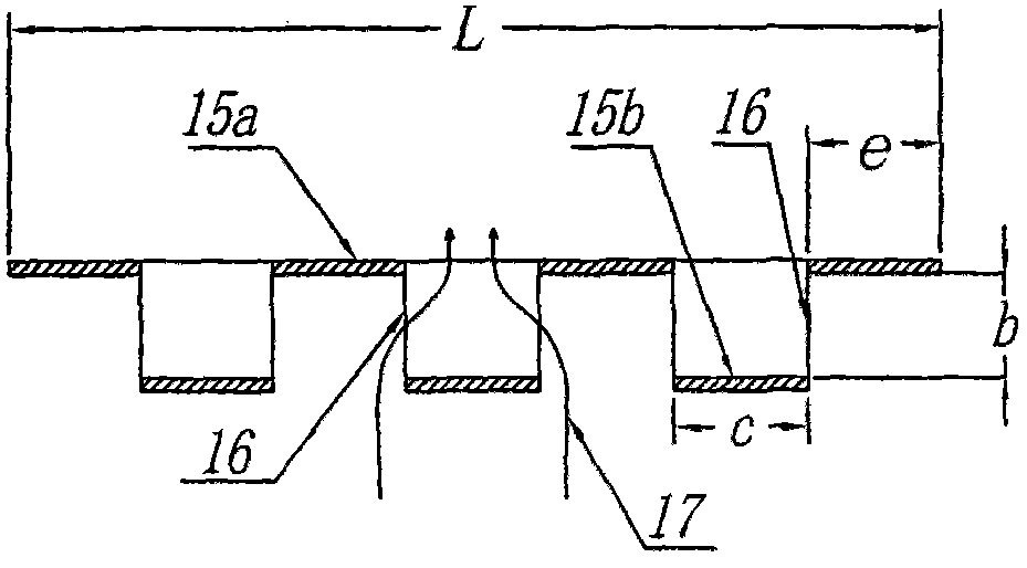

Image

  • Semiconductor light source radiator and light source engine
  • Semiconductor light source radiator and light source engine
  • Semiconductor light source radiator and light source engine

Examples


Embodiment Construction

[0027] specific implementation plan

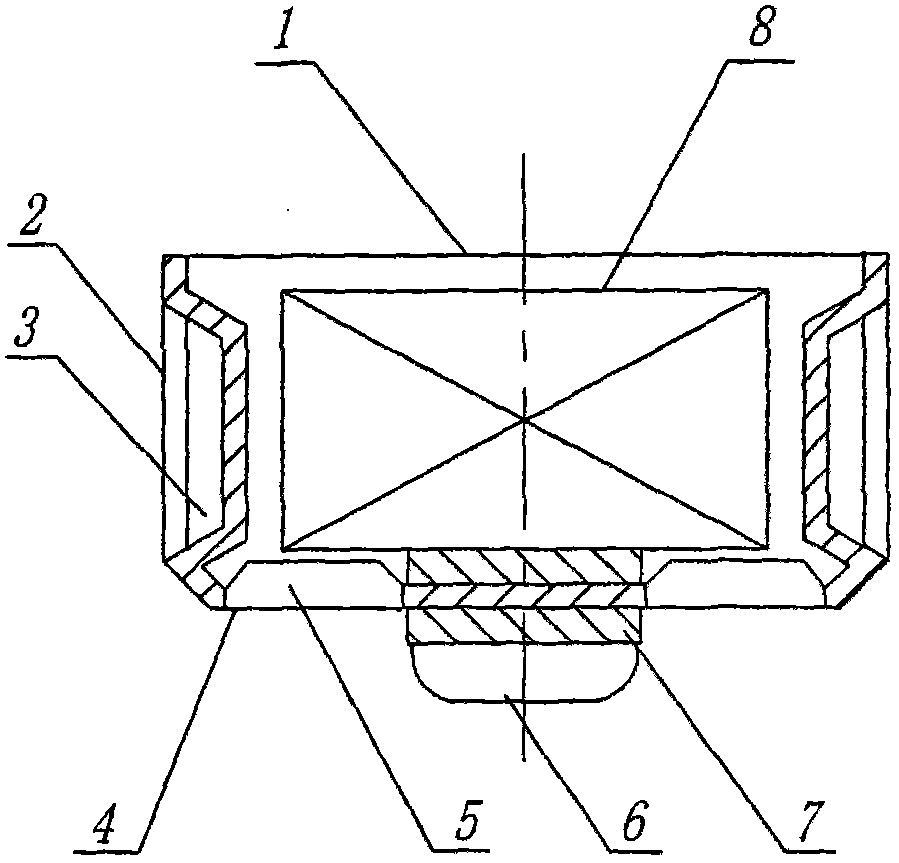
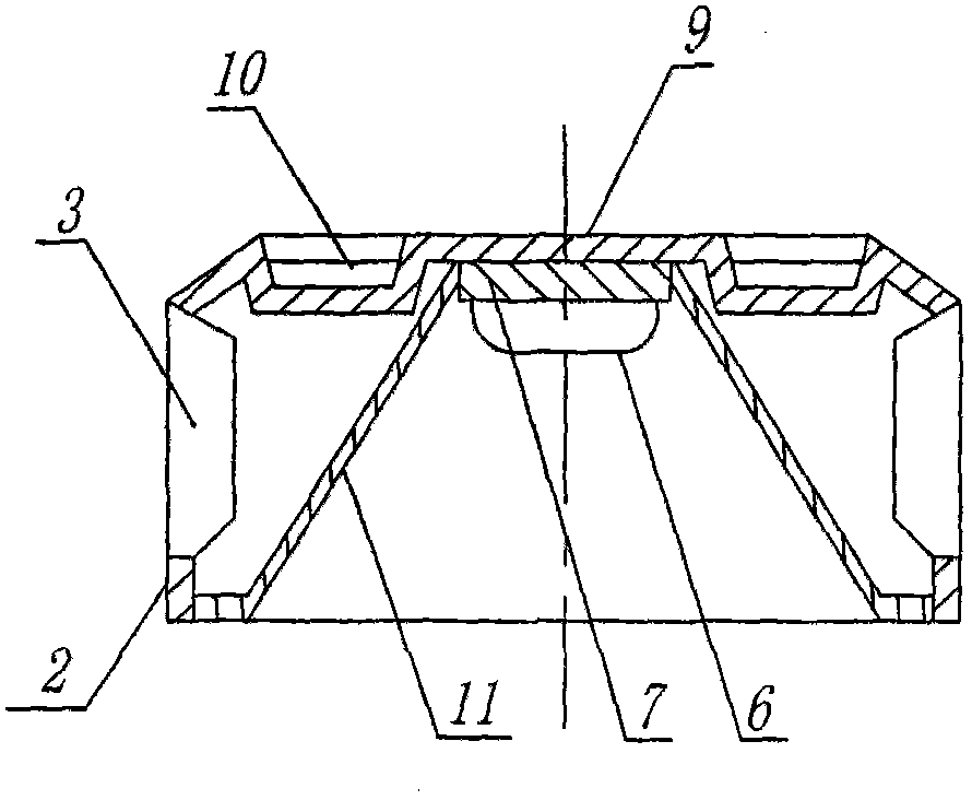
[0028] figure 1 In the shown semiconductor light source engine of the present invention, the metal side wall 2 of the heat dissipation metal shell 1 is an integral structure with the metal front shell 4, that is, it is made of the same metal plate, and the heat dissipation metal shell 1 is provided with a heat sink 8, and there is no metal in the figure. The rear shell and the metal side wall 2 are provided with a staggered ventilation window 3, the ventilation window 5 on the metal front shell 4 adopts a louver-like structure, and the semiconductor light source 6 is arranged on the heat conduction plate 7, which is directly attached to the heat conduction plate In the middle of the metal front shell 4, the contact surface between the middle of the metal front shell 4 and the heat conduction plate 7 is the contact heat transfer surface, here is the direct contact heat transfer surface. The heat generated by the semiconductor light source ...


PUM

PropertyMeasurementUnit
Average wall thicknessaaaaaaaaaa

Abstract

The invention aims to reduce the cost of a structural member and improve the heat dissipation performance, and provides a semiconductor light source radiator and a light source engine. The semiconductor light source engine is characterized in that a, the structure (the casing) serves as a cooling fin, namely a radiating metal casing (1) machined and formed through punching a sheet metal (aluminum plate), so that the machining cost and material cost are reduced; b, the wall thickness of the radiating metal casing is optimized to further reduce the material cost; c, the metal side wall (2) is formed through stretching a rear metal casing (9) or / and a front metal casing (4), a ventilating window (3) adopting a louver type or staggered arrangement type structure is formed, the ventilating ratio is not less than 0.20, so that air in natural convection flows smoothly, and the radiating performance is remarkably improved; and d, a reflector (31) is equipped, and most light emitted from a semiconductor light source (6) is light reflected by the reflector, so that the light source engine can solve the problem of dazzling light.

Description

technical field [0001] The invention belongs to the technical field of semiconductor light source heat dissipation and lighting, and in particular relates to a semiconductor light source radiator and a light source engine that adopt natural convection heat dissipation and use shell structural parts as heat sinks. technical background [0002] LED (semiconductor light source) is considered as the next-generation lighting source for human beings because of its energy saving and environmental protection. However, the key obstacle hindering the popularization of LED lighting lamps and replacing traditional lighting lamps is: the cost of LED lighting lamps is too high. The cost of LED lighting can be divided into three parts: LED light source, power supply and structural parts. The structural parts include radiators, and the cost of structural parts mainly comes from the radiators. At present, the cost of structural parts has accounted for as much as one-third of the total cost o...

Claims


Application Information

Patent Timeline
IPC IPC(8): F21V29/00F21Y101/02F21V29/50F21V29/70F21V29/89
Inventor 秦彪
Owner 秦彪
Why Eureka
Eureka Blog
Learn More