
An Adjustable Shear Resistant Structure Used in Large Travel Gear

A walking mechanism and adjustable technology, which is applied in the direction of the running mechanism, transport passenger cars, railway car body parts, etc., can solve the problems of being easily damaged by shear force, installation errors cannot be compensated, and wheels gnaw rails, etc., and the adjustment process is simple and convenient. Improving the effect of wheel gnawing and compensating for installation errors

Active Publication Date: 2015-12-16
JIANGSU GONGLI HEAVY MACHINERY
View PDF6 Cites 0 Cited by
  • Summary
  • Abstract
  • Description
  • Claims
  • Application Information

AI Technical Summary

Problems solved by technology

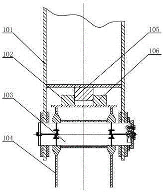
like figure 1 As shown, in general, the connection form of the traveling mechanism of the carts such as the ship unloader, ship loader, and door crane is that the balance beam 101 and the trolley frame 104 are hinged through the hinge shaft 103, but this connection mode is affected by the hinge shaft 103 When the force in the axial direction is easily damaged by shear force
The existing shear resistance forms are generally as follows: figure 1 As shown, the first shear block 102 and the second shear block 105 are welded at the hinge point between the balance beam 101 and the trolley frame 102, and the first shear block 102 is two pieces, which are arranged on the trolley frame 104 at intervals. The second shear block 105 is arranged between the two first shear blocks 102. The second shear block 105 is connected to the balance beam 101. The first shear block 102 and the second shear block 105 are closely attached and located in a line. On a straight line parallel to the hinge axis 103, but because the first shear block 102 and the second shear block 105 are not tightly bonded in this shear structure, the shear effect is poor and there is no adjustment capability. Once the wheel deviates from the center of the track, the position of the frame cannot be adjusted, the installation error cannot be compensated, and the phenomenon of wheel gnawing on the rail is prone to occur

Method used


Image

  • An Adjustable Shear Resistant Structure Used in Large Travel Gear
  • An Adjustable Shear Resistant Structure Used in Large Travel Gear

Examples


Embodiment Construction

[0014] The specific implementation manner of the present invention will be described below in conjunction with the accompanying drawings.

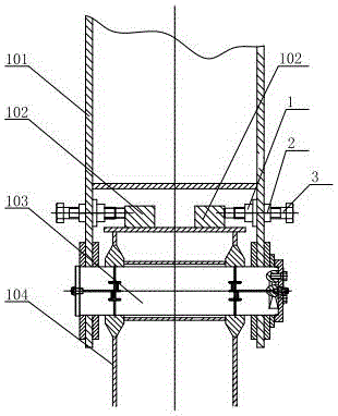
[0015] Such as figure 2 As shown, the present invention includes a balance beam 101. The balance beam 101 is flexibly connected to the trolley frame 104 through a hinge shaft 103, and two first shear blocks 102 are arranged symmetrically at intervals on the trolley frame 104. The diameter of the installation hole is larger than the diameter of the locking bolt 3 and the diameter of the fixing nut 1 by 1 mm to 3 mm. The fixed nut 1 is symmetrically welded on the inner wall of the balance beam 101 , the locking bolt 3 sequentially passes through the installation hole, the fixing nut 1 and abuts against the first shear block 102 , and the locking bolt 3 is fixed by the locking nut 2 . The fixed nut 1, the lock nut 2 and the lock bolt 3 are two sets, and the center point of the fixed nut 1, the lock nut 2 and the lock bolt 3 is the same as t...


PUM


Abstract

The invention relates to an adjustable shear resistant structure used for a large travelling mechanism, which comprises equalizing beams, wherein the equalizing beams are movably connected with a trolley frame by a hinged shaft; first shear resistant blocks are symmetrically arranged on the trolley frame at an interval; mounting holes are formed in the equalizing beams; inner walls of the equalizing beams are symmetrically connected with fixing nuts; locking bolts sequentially penetrate through the mounting holes and the fixing nuts, are propped against the first shear resistant blocks, and are fixed by locking nuts. According to the adjustable shear resistant structure, the fixing nuts are symmetrically welded on the inner walls of the equalizing beams, the locking bolts are screwed in and are propped against the first shear resistant blocks, and the locking bolts and the first shear resistant blocks are bonded tightly and fixed by the locking nuts, so that the locking bolts exert shear resistant actions on thrust of the first shear resistant blocks, and a shear resistant effect is better; and a relative position between the trolley frame and the equalizing beams can be changed by adjusting the locking bolts, so that the problem that a position of the trolley frame is nonadjustable due to the fact that a wheel deviates from a track center is solved, and a mounting error is compensated.

Description

technical field [0001] The invention relates to construction machinery equipment, in particular to an adjustable anti-shear structure used for large traveling mechanisms such as ship unloaders, ship loaders, door cranes and the like. Background technique [0002] With the development of my country's economy, the construction of ports is advancing by leaps and bounds, and the requirements for equipment such as ship unloaders, ship loaders, and door cranes are getting higher and higher. Such as figure 1 As shown, in general, the connection form of the traveling mechanism of the carts such as the ship unloader, ship loader, and door crane is that the balance beam 101 and the trolley frame 104 are hinged through the hinge shaft 103, but this connection mode is affected by the hinge shaft 103 When the force in the axial direction is easily damaged by the shear force. The existing shear resistance forms are generally as follows: figure 1 As shown, the first shear block 102 and ...

Claims


Application Information

Patent Timeline
Patent Type & Authority Patents(China)
IPC IPC(8): B61D15/00B65G67/60B66C9/16
Inventor 李钟马曙光
Owner JIANGSU GONGLI HEAVY MACHINERY
Learn More