Eureka AIR delivers breakthrough ideas for toughest innovation challenges, trusted by R&D personnel around the world.

Method and device for forming high-pressure and low-temperature jet flow by cutting coolant

A high pressure and low temperature, spray jet technology, applied in metal processing machinery parts, maintenance and safety accessories, metal processing equipment and other directions, can solve the problems of waste of resources, carcinogenicity, harmful substances, etc. Heat surface area, the effect of improving tool durability

Active Publication Date: 2013-09-11
NANJING UNIV OF AERONAUTICS & ASTRONAUTICS
View PDF7 Cites 21 Cited by
  • Summary
  • Abstract
  • Description
  • Claims
  • Application Information

AI Technical Summary

Problems solved by technology

But cutting fluid has great negative effects: First, it will threaten the health of workers
In order to improve the cooling and lubrication performance, most of the extreme pressure additives added to the cutting fluid are toxic, harmful substances, and even carcinogenic; the second is to cause serious pollution to the environment. , soil and air pollution; thirdly, the cost of cutting fluid accounts for an increasing percentage of processing costs; fourthly, this method has a large flow rate, wastes resources, and has very limited cooling and lubrication effects, which often cannot meet the needs of cooling, lubrication and environmental protection. needs

Method used


Image

  • Method and device for forming high-pressure and low-temperature jet flow by cutting coolant
  • Method and device for forming high-pressure and low-temperature jet flow by cutting coolant
  • Method and device for forming high-pressure and low-temperature jet flow by cutting coolant

Examples


Embodiment Construction

[0021] Below in conjunction with accompanying drawing, the present invention is further described:

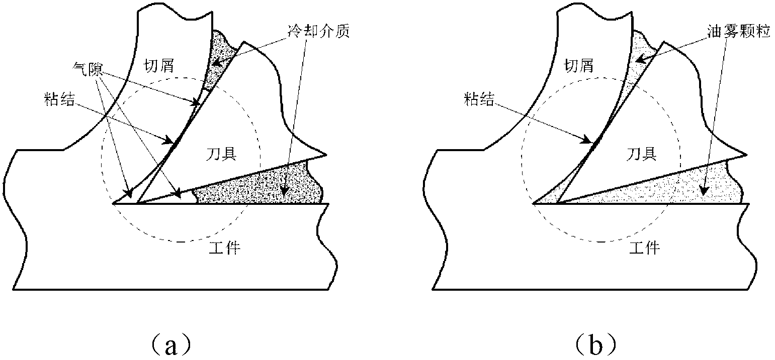
[0022] figure 1 It is a diagram of a high-pressure low-temperature spray jet cooling system. The device for forming a cutting cooling medium into a high-pressure low-temperature spray jet mainly consists of a gas storage tank 1, a filter 2, a dryer 3, a cooling device, a fluid container 7 and an atomizing nozzle 9. The dried and filtered gas is first stored in the gas storage tank 1, and the compressed gas in the gas storage tank 1 passes through the filter 2 and the dryer 3, and is connected to a tee pipe 4 through pipelines to divide into two gas paths. After passing through the cooling device 11, it becomes a low-temperature gas with a certain pressure, and the gas is connected to the gas inlet port (gas passage) of the pneumatic atomizing nozzle 9; the second gas passes into the liquid container 7 with good airtightness, and is pressed out by air pressure The liquid is inp...


PUM


Abstract

The method discloses a method and device for forming high-pressure and low-temperature jet flow by cutting coolant. The method includes that compressed air stored inside an air storage tank is filtered and dried and connected to a tee joint through a hose to divide an output pipe into two branches, air in one branch is cooled by a cooling device to become low-temperature high-pressure air, and inputted into an air inlet end of a pneumatic spray nozzle after being connected with one or more than one tee joint, the air in the other branch is inputted into a well-sealed cutting fluid storage container after pressure in the air is regulated by a pressure regulating valve, the cutting fluid is pressed out, and connected into liquid inlet ends of a plurality of pneumatic spray nozzles after passing one or more than one tee joint prior through the hose, the air and the liquid are mixed outside a jet nozzle to produce high-speed jet flow. By the method, usage amount of cooling lubricating liquid is reduced, cooling and lubricating functions of fluid medium are fully performed, cutting temperature is greatly lowered, and tool durability is conspicuously improved.

Description

[0001] technical field [0002] The invention relates to the technical field of high-efficiency cooling and lubrication, in particular to a cooling method and a cooling device in cutting and grinding. Background technique [0003] At present, most enterprises still use the traditional cooling method, that is, pouring cutting fluid to cool and lubricate the cutting area to reduce the cutting temperature and improve the tool life and processing quality. But cutting fluid has great negative effects: First, it will threaten the health of workers. In order to improve the cooling and lubrication performance, most of the extreme pressure additives added to the cutting fluid are toxic, harmful substances, and even carcinogenic; the second is to cause serious pollution to the environment. , soil and air pollution; thirdly, the cost of cutting fluid accounts for an increasing percentage of processing costs; fourthly, this method has a large flow rate, wastes resources, and has very l...

Claims


Application Information

Patent Timeline
Patent Type & Authority Applications(China)
IPC IPC(8): B23Q11/10
Inventor 徐九华丁文锋吕东升傅玉灿马晓迪杨长勇
Owner NANJING UNIV OF AERONAUTICS & ASTRONAUTICS
Why Eureka
Eureka Blog
Learn More