Power-adjustable rectifying circuit

A rectifier circuit and circuit technology, applied in the field of electronic circuit analysis and production, can solve the problems of low power, unstable performance, high maintenance, etc., and achieve the effects of stable performance and simple structure

Inactive Publication Date: 2013-09-04
SHANTOU UNIV
View PDF2 Cites 4 Cited by
  • Summary
  • Abstract
  • Description
  • Claims
  • Application Information

AI Technical Summary

Problems solved by technology

[0002] The process of converting alternating current into direct current is called rectification. In daily life and industrial production, many electrical equipment need adjustable direct current power. However, the current direct current power in the prior art is generally fixed power, or its power is small and adjustable. The adjusted output power range is small, the switching loss of the circuit is large, a variety of components are used, the wiring is complicated, the performance is unstable, and the maintenance cost is high.

Method used


Image

  • Power-adjustable rectifying circuit

Examples


Embodiment 1

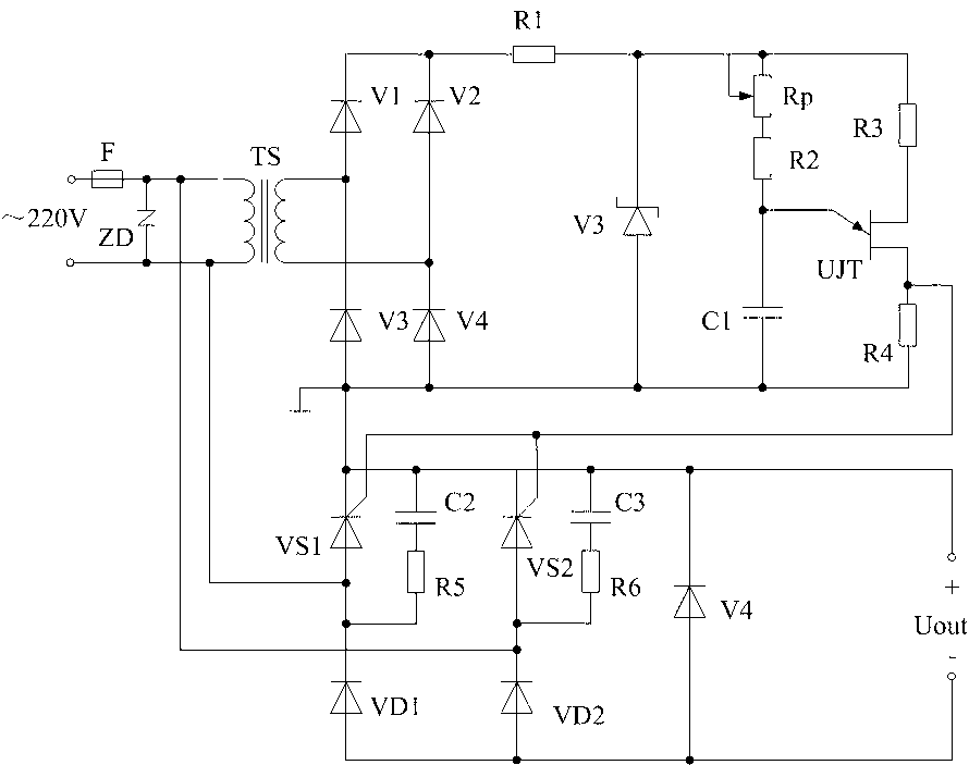
[0027] The embodiment of the present invention provides the power control part and AD conversion part used in the electromagnetic heating circuit. Using such a circuit structure can greatly simplify the circuit structure, and reduce the synchronous circuit compared with the conventional electromagnetic heating circuit structure, because the power control part and The AD conversion part can be replaced by this unijunction transistor pulse-triggered rectification circuit, which can synchronize the leading edge of the switching pulse on the G pole with the trailing edge of the pulse voltage generated on the UJT. The power control method of the present invention is simpler and more practical than the conventional electromagnetic heating control method, and the switching power consumption of the transistor switch circuit is small, light in weight, less in wiring, convenient in maintenance, and less in failure; conventional electromagnetic heating needs a single-chip microcomputer or ...

Embodiment 2

[0029] The embodiment of the present invention provides a speed regulation system applied to a separately excited DC motor, and the load connected to the rectification circuit is a resistive inductive load. Add a trigger pulse to the thyristor VS1 at the trigger angle α of the positive half cycle of the mains to turn it on. The voltage of the output voltage Uout is equal to the mains voltage. There is an inductance in the load so that the load current cannot change abruptly, and the inductance will level off the load current. Wave action, assuming that the load inductance is large, the load current is continuous and the waveform is approximately a horizontal line. When the mains power turns negative when it crosses zero, the thyristor VS1 and the diode VD2 still flow through the current due to the effect of the inductance and do not turn off. At the time of wt=π+α, a trigger pulse is added to the thyristor VS2, and the thyristor is turned on because VS2 has been subjected to a...


PUM


Abstract

The embodiment of the invention discloses a power-adjustable rectifying circuit, comprising a rectifying circuit and a triggering circuit; the rectifying circuit comprises two thyristors and two diodes, which form a first rectifying bridge circuit connected to a mains supply; the triggering circuit comprises a relaxation oscillation circuit formed by unijunction transistors; the relaxation oscillation circuit is provided with an RC oscillation circuit and an adjustable resistor capable of adjusting oscillation frequency; and the triggering circuit also comprises a synchronous transformer, a second rectifying bridge circuit connected with the synchronous transformer and a voltage-regulator tube for performing clipping on the second rectifying bridge circuit to power the relaxation oscillation circuit. After the power-adjustable rectifying circuit is adopted, switch control signals of the thyristors are provided for the rectifying circuits by the synchronous triggering circuit, thus enabling the power size of the output circuit of the rectifying circuit to be adjustable. The power-adjustable rectifying circuit can be used as a control unit for power controlling, can be used for the non-polar speed adjusting of a motor and the power control unit for electromagnetic heating, and is simple in structure and stable in performance.

Description

technical field [0001] The invention relates to the field of analysis and manufacture of electronic circuits, in particular to a rectifier circuit for adjusting power through pulse phase shifting. Background technique [0002] The process of converting alternating current into direct current is called rectification. In daily life and industrial production, many electrical equipment need adjustable direct current power. However, the current direct current power in the prior art is generally fixed power, or its power is small and adjustable. The adjusted output power range is small, the switching loss of the circuit is large, various components are used, the wiring is complicated, the performance is unstable, and the maintenance cost is high. [0003] The single-phase semi-controlled rectifier circuit composed of thyristors can convert alternating current into direct current with controllable size, so as to achieve the purpose of adjustable direct current voltage. Moreover, t...

Claims


Application Information

Patent Timeline
Patent Type & Authority Applications(China)
IPC IPC(8): H02M7/219H02M1/088
Inventor 贺长林陈少克
Owner SHANTOU UNIV
Why Eureka
Try Eureka