
Method for calculating failure critical clearing time based on critical unit pair

A technology of critical cut-off time and calculation method, applied in the direction of AC network circuits, electrical components, circuit devices, etc., can solve the problems of inability to adapt to online analysis, long calculation time of time domain simulation methods, etc., to reduce the data processing process and calculation speed. Fast, visible results

Inactive Publication Date: 2013-09-04
HARBIN ENG UNIV
View PDF3 Cites 8 Cited by
  • Summary
  • Abstract
  • Description
  • Claims
  • Application Information

AI Technical Summary

Problems solved by technology

However, the time-domain simulation method cannot meet the requirements of online analysis due to the long calculation time; although the extended equal-area method can improve the calculation speed, it depends on the correctness of cluster clustering, and the identification of critical clusters is still not very good. was solved; although the calculation speed of the transient energy function method is much faster than that of the time-domain simulation method, the method itself has a huge demand for system information. During the iterative calculation process, it is necessary to obtain the transient state of all generators process data

Method used

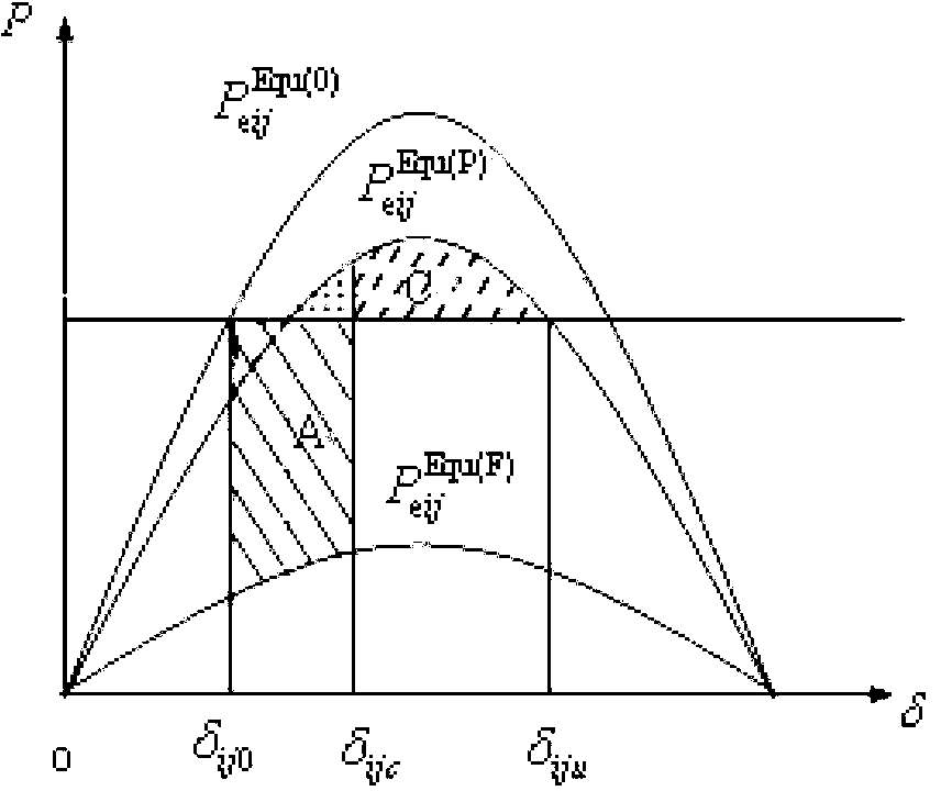

Image

  • Method for calculating failure critical clearing time based on critical unit pair
  • Method for calculating failure critical clearing time based on critical unit pair
  • Method for calculating failure critical clearing time based on critical unit pair

Examples


Embodiment Construction

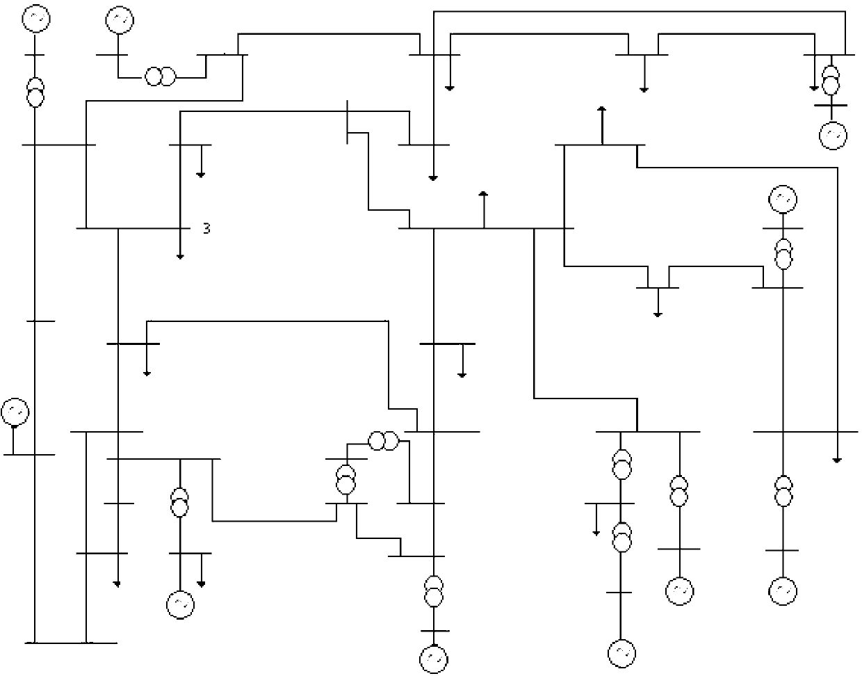
[0015] The specific implementation steps of the present invention will be described below in conjunction with examples. This implementation is carried out in the New England 10-machine 39-node system. The wiring diagram of the system is as follows figure 2 shown.

[0016] Step 1: Obtain the expected accident set under the current power grid operation state from the power dispatching department, and extract a fault from the expected accident set. Assuming that the acquired fault is a three-phase-to-ground short circuit at node 3, t clmax =0.27 seconds to remove the fault.

[0017] Step: 2: Select the critical unit pair

[0018] The method of selecting the critical unit pair is as follows:

[0019] If Ωcr is recorded as the critical cluster set and Ωnon-cr is the remaining cluster set, then for any i∈Ωcr, j∈Ωnon-cr, the pair (i, j) is called a “critical unit pair”. The critical unit pair selection steps are as follows:

[0020] (1) Transient numerical simulation of the sy...


PUM


Abstract

The invention discloses a method for calculating a failure critical clearing time based on a critical unit pair. The method comprises the following steps of collecting all the running parameter data of a power system by a wide-area phase measuring system to form a data file; for each failure in a predicted event set provided by a scheduling department, simulating the transient values of the power system by maximum clearing time based on the data file to generate simulated data; selecting a critical unit pair according to the simulated data; judging the stability of the critical unit pair and finally judging the stability of the power system; dividing failures into instability failures and stability failures according to the judging results of the stability; calculating the critical clearing time of the critical unit pair if the failures belong to the instability failures; and calculating the critical clearing time of the power system. The method has the advantages that the values of the critical unit groups and the critical units about agglomeration and the like do not need to be recognized, the critical clearing time of the system can be obtained based on the data of few generators in the power system, and the calculation process is simple and fast.

Description

technical field [0001] The invention relates to the technical field of power system stability and control, in particular to a calculation method for critical cut-off time under fault based on a critical unit pair. Background technique [0002] Critical Clearing Time (CCT) refers to the latest clearing time that can keep the system stable in the event of a power system failure. Fault critical removal time is a common index to characterize the transient stability of the system. The larger the CCT, the stronger the system's ability to resist external impacts, and it provides an important operating basis for operators. Therefore, an important content in the study of transient stability is how to calculate CCT quickly and accurately. Due to the increase of operating modes in large power grids and the increase of predicted accident sets, the calculation of CCT takes a lot of time. Therefore, it is particularly important to increase the calculation speed of a single CCT to shorten...

Claims


Application Information

Patent Timeline
Patent Type & Authority Applications(China)
IPC IPC(8): H02H7/26H02J3/00
Inventor 卢芳刘宏达兰海黄曼磊张敬南李军程鹏张强
Owner HARBIN ENG UNIV
Learn More