
Manufacturing method for machine vision filter

A production method and machine vision technology, applied in the direction of optical filters, etc., can solve the problem of long horizontal image distance, etc., and achieve the effect of satisfying small volume

Inactive Publication Date: 2013-09-04
上海汇珩信息科技有限公司
View PDF0 Cites 5 Cited by
  • Summary
  • Abstract
  • Description
  • Claims
  • Application Information

AI Technical Summary

Problems solved by technology

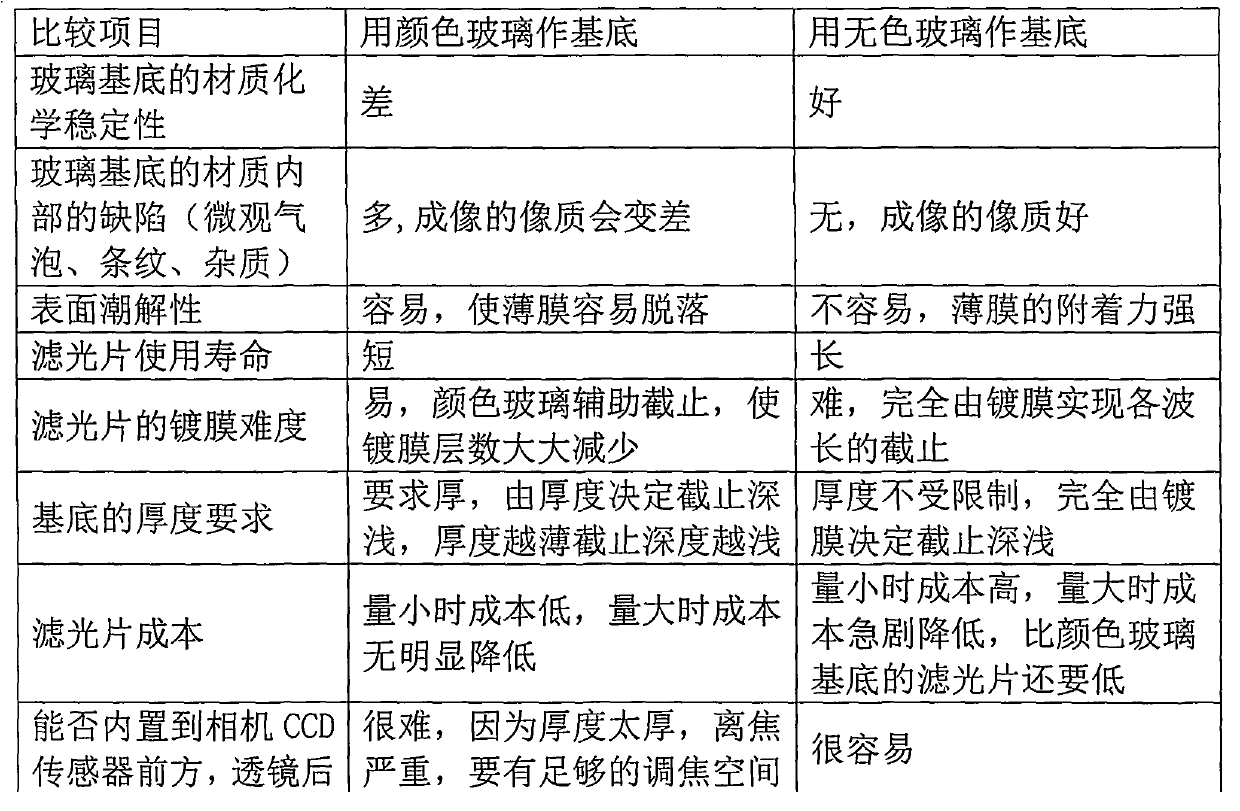
In China, the level of coating equipment and coating technology is generally low. Most optical film manufacturers can only produce filters with relatively simple coating layers. There are very few manufacturers that can produce narrow-band filters, and they can only rely on colored glass. As the substrate, the design and plating with fewer film layers are far from the level of foreign countries.

Method used


Image

  • Manufacturing method for machine vision filter
  • Manufacturing method for machine vision filter
  • Manufacturing method for machine vision filter

Examples


Embodiment Construction

[0026] A method for making a machine vision filter, the steps are as follows:

[0027] A. Cutting: Cut the glass substrate according to the size required by the equipment, and the glass substrate is a colorless glass substrate;

[0028] B. Cleaning: Soak the cut glass substrate in pure water, and use ultrasonic waves for vibration cleaning;

[0029] C. Drying: Dry the cleaned glass substrate by air drying;

[0030] D. Coating the main film: Put the glass substrate into the coating chamber, pump the vacuum of the coating chamber to 0.003Pa, preheat the glass substrate temperature to 320°C, turn on the process gas and the Hall ion source, The main film is plated by ion beam assisted electron beam evaporation coating process;

[0031] E, plating secondary film: after plating the main film, use the same process as in step D to plate the secondary film on the other side of the glass substrate;

[0032] F. Post-processing: Use an inner circle cutting machine to grind the coated g...


PUM


Abstract

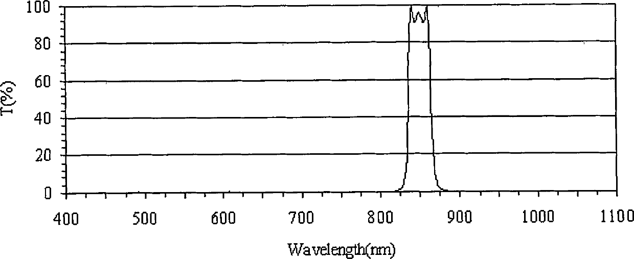
The invention discloses a manufacturing method for a machine vision filter. The manufacturing method comprises the following steps: A, cutting, i.e., cutting a glass substrate according to the required size of equipment, wherein the adopted glass substrate is a colorless glass substrate; B, cleaning, i.e., placing the cut glass substrate in pure water to soak and performing oscillation cleaning by using ultrasonic wave; C, drying, i.e., drying the cleaned glass substrate by using an air drying method; D, plating a main film, i.e., plating the main film by using an ion beam assisted electron beam evaporation coating technology; E, plating a secondary film, i.e., plating the secondary film on the other face of the glass substrate by using the same process in the step D after plating the main film; and F, post-processing, i.e., grinding the edge of the plated glass substrate by using an inner circle cutting machine. According to the manufacturing method, the cost for manufacturing the machine vision filter is greatly reduced by using a series of scientific manufacturing processes, and the signal-noise ratio of the machine vision filter has reached the level of 1,000:1.

Description

technical field [0001] The invention relates to the technical field of vacuum coating, in particular to a method for manufacturing a machine vision filter. Background technique [0002] Due to the continuous development of optical imaging technology and the continuous improvement of automation requirements for various systems, equipment or instruments, machine vision has emerged as an emerging field, such as in various security monitoring fields based on face recognition, and license plate recognition. Basic intelligent traffic management, intelligent robots based on shape and position measurement, production line quality assurance, high-risk operations and other fields. The machine vision system is characterized by improving the flexibility and automation of production. In some dangerous working environments that are not suitable for manual work or where artificial vision is difficult to meet the requirements, machine vision is often used to replace artificial vision; at t...

Claims


Application Information

Patent Timeline
Patent Type & Authority Applications(China)
IPC IPC(8): G02B5/20C03C17/00
Inventor 韩秀峰朱凯敏
Owner 上海汇珩信息科技有限公司
Learn More