
Low-pollution combustor for emission reduction through hydrogenation during aviation fuel combustion

A technology of aviation fuel and combustion chamber, which is applied in the direction of combustion chamber, continuous combustion chamber, combustion method, etc., to achieve the effect of ensuring combustion stability, easy adjustment and matching, and strong flexibility

Active Publication Date: 2013-09-04
BEIHANG UNIV
View PDF21 Cites 10 Cited by
  • Summary
  • Abstract
  • Description
  • Claims
  • Application Information

AI Technical Summary

Problems solved by technology

[0020] The problem to be solved by the present invention is to overcome the deficiencies of the existing technology, and to provide a low-pollution combustion chamber for aviation gas turbines used in aviation fuel hydrogenation and auxiliary combustion by using premixed pre-evaporation extremely lean combustion technology. The head adopts pre-combustion stage and Central staged combustion of the main combustion stage adopts hydrogenation auxiliary combustion measures to ensure the efficiency and stability of extremely lean combustion, expand the limit of lean combustion, reduce the temperature of the combustion zone and combustion pulse, and reduce the emission of nitrogen oxides and NOx pollution under various working conditions. Further significantly reduce emissions from aero-engines throughout the landing-takeoff LTO cycle

Method used


Image

  • Low-pollution combustor for emission reduction through hydrogenation during aviation fuel combustion
  • Low-pollution combustor for emission reduction through hydrogenation during aviation fuel combustion
  • Low-pollution combustor for emission reduction through hydrogenation during aviation fuel combustion

Examples


Embodiment Construction

[0043] The present invention will be further described below in conjunction with the accompanying drawings and specific embodiments.

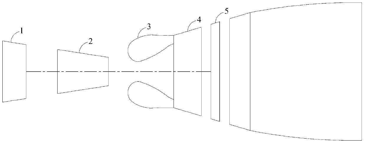
[0044] figure 1 It is a schematic diagram of the engine structure, including a low-pressure compressor 1, a high-pressure compressor 2, a combustion chamber 3, a high-pressure turbine 4 and a low-pressure turbine 5. When the engine is working, the air is compressed by the low-pressure compressor 1 and enters the high-pressure compressor 2. The high-pressure air then enters the combustion chamber 3 to burn with fuel. The high-temperature and high-pressure gas formed after combustion enters the high-pressure turbine 4 and low-pressure turbine 5, and passes through the turbine. Work is done to drive the high-pressure compressor 2 and the low-pressure compressor 1 respectively.

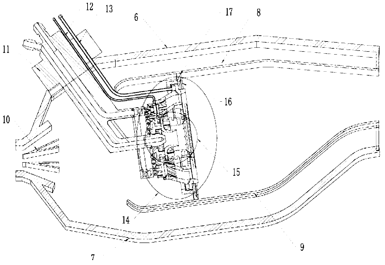
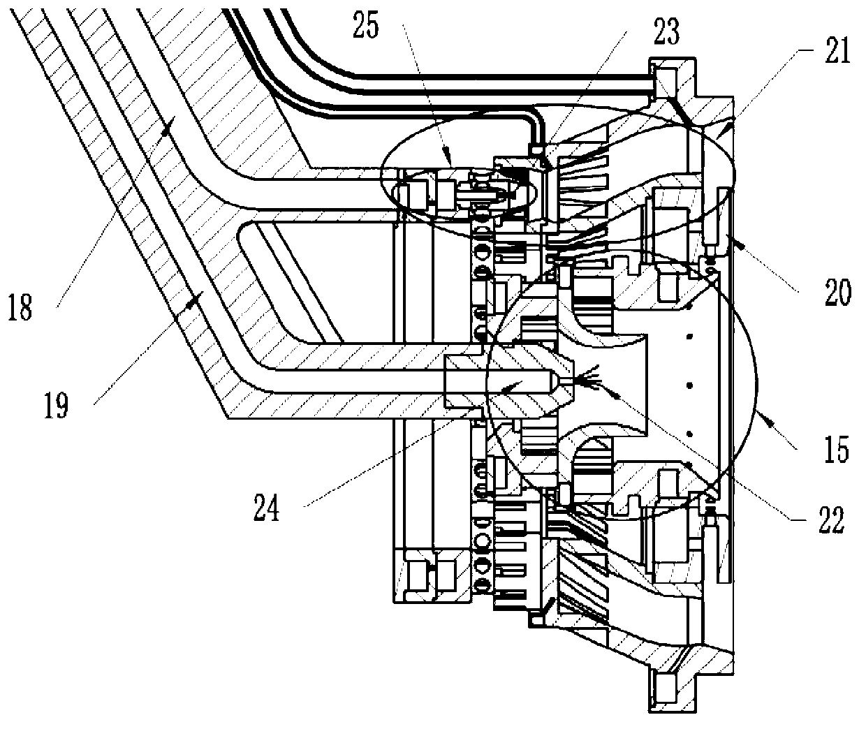
[0045] figure 2 It is a cross-sectional view of the combustion chamber structure. The low-pollution combustion chamber adopts a single-ring cavity structure, which is c...


PUM


Abstract

The invention relates to a low-pollution combustor for emission reduction through hydrogenation during aviation fuel combustion. As a whole, the combustor adopts a premixed lean combustion mode, wherein the head portion of the combustor adopts the mode that a preliminary combustion stage center and a main combustion stage center are in staged combustion, and the overall structure of a flame tube is a single-ring cavity. A preliminary combustion stage adopts a diffusive combustion mode to guarantee stable combustion. A main combustion stage adopts a premixed combustion to lower pollutant discharge of large working conditions. The preliminary combustion stage and the main combustion stage can adopt a hydrogenation auxiliary combustion mode respectively or simultaneously, therefore, the efficiency and the stability of extremely lean combustion are guaranteed, the limit of the lean combustion is expanded, the temperature and the combustion pulsation in a combustion zone are reduced, and the purpose of reducing the pollutant discharge of nitric oxides NOx is achieved. According to the low-pollution combustor for the emission reduction through the hydrogenation during the aviation fuel combustion, hydrogenation assistance is conducted on the aviation fuel combustion, the pollutant discharge of NOx is lowered substantially through the extremely lean consumption, the fuel is mainly aviation fuel, the hydrogenation only plays a role in assisting combustion, the total consumption of hydrogen is low, and the requirement for the improvement of an engine and aircraft hardware is low. The low-pollution combustor has the advantage of fuel flexibility.

Description

technical field [0001] The invention relates to the technical field of aviation gas turbines, in particular to a low-pollution combustor for hydrogenation in the combustion of aviation fuel, which enhances the lean combustion stability of aviation fuel through hydrogenation combustion, and can burn efficiently and stably in an extremely lean state. To achieve the purpose of reducing pollution emissions such as nitrogen oxides without reducing combustion efficiency, and at the same time meet the requirements of future low-pollution combustion chambers for fuel flexibility. The invention is beneficial to reduce the pollution emission of the aero-engine landing-take-off cycle (Landing and Take-off, LTO), and ensure the safe and reliable operation of the engine under all working conditions. Background technique [0002] In response to local human health and global climate change, the main development requirements of modern civil aeroengine combustors are safety and environmental...

Claims


Application Information

Patent Timeline
Patent Type & Authority Applications(China)
IPC IPC(8): F23R3/28F23R3/02
Inventor 张弛于博文林宇震康尧许全宏
Owner BEIHANG UNIV
Learn More