
A rotary razor

A shaver, rotary technology, applied in the field of electric rotary shavers, can solve the problems of unsatisfactory rotation trajectory, small moving blade surface, large jitter, etc., to achieve stability and non-interference, simple production process, Good concentricity

Active Publication Date: 2015-09-09
宁波美钻机电有限公司
View PDF9 Cites 0 Cited by
  • Summary
  • Abstract
  • Description
  • Claims
  • Application Information

AI Technical Summary

Problems solved by technology

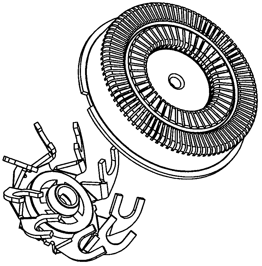
like figure 1 As shown, in the prior art, because the groove on the fixed knife net is very deep to form an included angle, the knife surface of the moving knife is small, the efficiency is low, and it is easy to pull the beard, especially the beard passing by the side, there is always shaving residue
In addition, the moving knives are erected on the support base plate through a support rod. Generally, two groups of moving knives are supported by a U shape on a support rod. On the one hand, each moving knife is independent, that is, it is set by a different support rod In this way, during production, the concentricity cannot be well controlled, and two sets of knives are set on each support rod. As long as one set of moving knives tilts and cannot shave, it will definitely affect the other set of moving knives.
Therefore, when the movable knife with this structure rotates, the rotation trajectory is not ideal, the work is not stable, and the vibration is large.

Method used


Image

  • A rotary razor
  • A rotary razor
  • A rotary razor

Examples


Embodiment 1

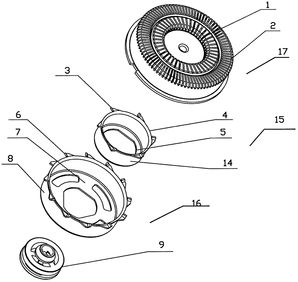
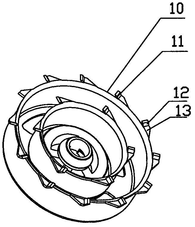
[0017] Embodiment one: if figure 2 , 3 Shown, a kind of rotary shaver includes a razor body and a cutter head arranged on the razor body, the cutter head includes a fixed knife net 17 and a moving knife assembly arranged below the fixed knife net, and the dynamic The knife assembly includes a first movable knife assembly 15 and a second movable knife assembly 16, the first movable knife assembly 15 includes a first support base plate 5, and the outer edge of the first support base plate 5 extends upwards with a support wall 4, and the support wall 4 First movable knives 3 are evenly spaced on the outer side of the circumferential direction, and the second movable knife assembly 16 includes a second support base plate 7, and a second support wall 8 extends upward from the outer edge of the second support base plate 7. The second movable knives 6 are evenly spaced on the outer side of the second support wall 8 . The first moving knife 3 and the second moving knife 6 all inclu...

Embodiment 2

[0021] Embodiment two: a kind of rotary shaver is a single-ring shaver, and other structures are the same as in embodiment one, including a shaver body and a cutter head arranged on the shaver body, and the cutter head includes a fixed blade The net 18 and the moving knife assembly arranged under the fixed knife knife net correspond to a single-ring razor, and the moving knife assembly only includes a moving knife 20, that is, only a supporting base plate and the moving knife on the supporting base plate. The outer edge of the support base plate extends upwards to be provided with a support wall 19, and the circumferential outer side of the support wall is evenly spaced with movable knives 20, the movable knife includes a knife body and a knife edge, and the knife body of the movable knife extends laterally outwards from the support wall, and The width of the knife body gradually increases from the rear to the side of the knife edge, the knife edge is bent upwards, that is, it ...


PUM


Abstract

The invention relates to a rotary shaver. The rotary shaver comprises a shaver body and a shaver head which is arranged on the shaver body; the shaver head comprises a stationary cutter net and a moving cutter assembly which is arranged under the stationary cutter net; the moving cutter assembly comprises a supporting bottom plate and moving cutters; the moving cutters are arranged on the supporting bottom plate; the outer edge of the supporting bottom plate extends upwards to form into a supporting wall; a circumferential external side of the supporting wall is provided with the moving cutters in an interval mode; the moving cutters comprise cutter bodies and cutter edges; the cutter edges of the moving cutters are upwardly arranged in an inclined mode; and the supporting wall between the moving cutters forms into a capture ring. According to the rotary shaver, the supporting wall is arranged on the supporting bottom plate of the moving cutter assembly and the moving cutters are arranged on the outer edge of the supporting wall, so that the concentricity of the moving cutters is good, the operation is stable, the production technology is simple, the capture ring which is formed by the supporting wall can capture and shave off beards on the bilateral sides, and the beards cannot be pulled.

Description

(1) Technical field [0001] The invention relates to an electric rotary shaver. (2) Background technology [0002] The cutter head of the electric rotary shaver generally includes a mesh cover composed of a circular fixed knife net, and a moving knife assembly is arranged below it. The center of the knife rotates to drive the knife to shave off the beard. Such as figure 1 As shown, in the prior art, because the groove on the fixed knife knife net is very deep and forms an included angle, the knife surface of the moving knife is relatively small, and the efficiency is low, and it is easy to pull beards, especially the beards passing by on the side, and there are always shaving residues. In addition, the moving knives are erected on the support base plate through a support rod. Generally, two groups of moving knives are supported by a U shape on a support rod. On the one hand, each moving knife is independent, that is, it is set by a different support rod In this way, during...

Claims


Application Information

Patent Timeline
Patent Type & Authority Patents(China)
IPC IPC(8): B26B19/14B26B19/38
Inventor 陆匡业
Owner 宁波美钻机电有限公司
Learn More