
Method for dynamically monitoring torque of main milling head of numerical-control floor type boring and milling machine

A dynamic monitoring, milling and boring machine technology, applied in metal processing mechanical parts, measuring/indicating equipment, metal processing equipment, etc., can solve the damage accuracy of the main milling head and the attachment milling head, can not truly reflect the maximum torque value, ignore the rated torque Limits and other issues to avoid damage or precision damage, easy to operate and master, and less time-consuming

Active Publication Date: 2015-06-17
JIER MACHINE TOOL GROUP
View PDF8 Cites 0 Cited by
  • Summary
  • Abstract
  • Description
  • Claims
  • Application Information

AI Technical Summary

Problems solved by technology

However, the fixed value limit cannot truly reflect the maximum torque value that the main milling head can withstand at a certain position of the boring bar or ram
[0004] The current CNC floor milling and boring machines often ignore the rated torque limit of the main milling head and accessory milling head, overloading the main milling head and accessory milling head will cause damage or precision damage to the main milling head and accessory milling head

Method used


Image

  • Method for dynamically monitoring torque of main milling head of numerical-control floor type boring and milling machine
  • Method for dynamically monitoring torque of main milling head of numerical-control floor type boring and milling machine
  • Method for dynamically monitoring torque of main milling head of numerical-control floor type boring and milling machine

Examples


Embodiment Construction

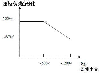
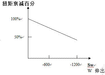
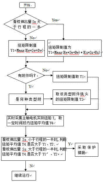
[0024] The dynamic monitoring method of the torque of the main milling head of the CNC floor-type milling and boring machine of the present invention is to calculate the torque attenuation caused by the extension of the boring bar and the ram, and at the same time use the numerical control function to collect the actual torque of the main milling head in real time, and within the set time The actual torque of the main milling head is compared with the calculated allowable torque in real time, and dynamically monitored to limit the torque of the main milling head within the allowable range.

[0025] Such as image 3 As shown, the embodiment is now described: firstly, the characteristic curve t1 between the displacement of the boring bar in the W-axis direction and the torque attenuation percentage of the main milling head and the displacement of the ram in the Z-axis direction and the torque attenuation of the main milling head are respectively established. Characteristic curve...


PUM


Abstract

The invention discloses a method for dynamically monitoring torque of a main milling head of a numerical-control floor type boring and milling machine. The method is characterized in that torque attenuation caused by the fact that a boring bar and a ram extend is computed; actual torque of the main milling head is acquired in real time by the aid of a numerical-control function; the actual torque of the main milling head is compared to computed permissible torque and is dynamically monitored within set time; and the torque of the main milling head is limited within a permissible range. The method has the advantages that an integral control procedure can be operated and mastered conveniently, and elapsed time is short; damage to the main milling head and an accessory milling head or damage to the precision of the main milling head and the precision of the accessory milling head due to the fact that the main milling head and the accessory milling head run in overload states is prevented; and a shaft of a machine tool is protected and is stressed within a permissible range, and the accuracy life of the machine tool is prolonged.

Description

technical field [0001] The invention relates to a method for dynamically monitoring the torque of a main milling head of a numerical control floor milling and boring machine. Background technique [0002] The boring bar on the CNC floor milling and boring machine is located in the ram. Both the boring bar and the ram can be moved telescopically. The boring bar protrudes outward in the direction of the W axis. The torque of the main milling head will decay according to the law as the boring bar extends out. The longer the stick out, the greater the torque decay. If the boring bar performs high-torque cutting at a position with a large extension, exceeding its allowable torque limit value, the boring bar will vibrate severely, affecting the accuracy of the boring bar and thus affecting the machining accuracy. Therefore, it is necessary to limit the torque of the main milling head according to the position of the boring bar. . Similarly, when the ram protrudes outward in the ...

Claims


Application Information

Patent Timeline
Patent Type & Authority Patents(China)
IPC IPC(8): B23Q17/09
Inventor 曲改玉周辉
Owner JIER MACHINE TOOL GROUP
Learn More