
Automobile hub bore numerical control milling device

An automotive wheel hub, CNC milling technology, applied in feeding devices, metal processing, metal processing equipment and other directions, can solve the problems of expensive equipment and complex structure, and achieve the effect of facilitating rapid movement, improving machine tool accuracy, and uniform force

Active Publication Date: 2013-09-04
JIANGSU SLD PRECISION TECH
View PDF6 Cites 41 Cited by
  • Summary
  • Abstract
  • Description
  • Claims
  • Application Information

AI Technical Summary

Problems solved by technology

[0003] The hub hole coefficient controlled milling processing device imported from abroad has a complex structure and expensive equipment, and the existing processing device cannot well meet the current processing needs.

Method used


Image

  • Automobile hub bore numerical control milling device
  • Automobile hub bore numerical control milling device
  • Automobile hub bore numerical control milling device

Examples


Embodiment 1

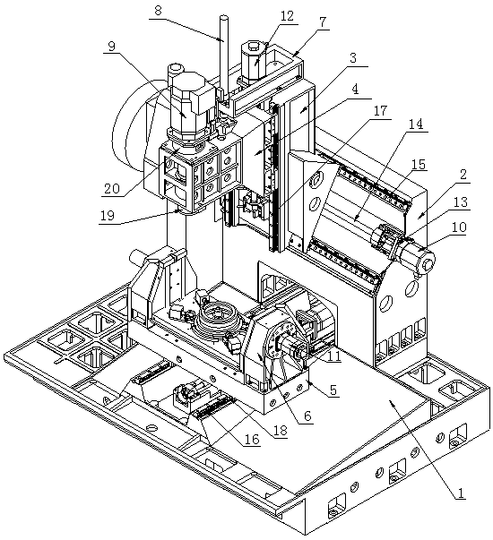
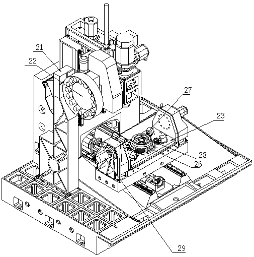
[0030] Such as figure 2 , image 3 As shown, the automobile hub hole coefficient controlled milling processing device of the present invention includes a base 1, a column 2, a tool magazine 22, a spindle motor 9, a spindle 19, and a spindle box 4. The column 2 is installed on the base 1, and the tool magazine 22 passes through the tool The library bracket 21 is installed on the base 1, and the main shaft 19 is connected with the main shaft motor 9.

[0031] A Y-axis screw 14 is installed on the base 1 in the front-to-rear direction, and the Y-axis screw 14 is connected to the Y-axis motor 10; the base 1 is also provided with a Y-axis sliding table 5, and the bottom of the Y-axis sliding table 5 has a nut seat, The nut seat is assembled with the Y-axis screw, the mating surface of the base 1 and the Y-axis sliding table is also assembled through the Y-axis guide 16 and the Y-axis slider 18, the Y-axis guide 16 and the Y-axis slider 18 are assembled with The Y-axis screw is arrang...

Embodiment 2

[0042] The workflow of the present invention:

[0043] Properly adjust the position of the hydraulic clamp 27 to make it possible to process the appropriate wheel shape, and place the aluminum alloy wheel hub on the center expansion sleeve 26 for preliminary positioning. Press the system operation panel to start the switch and the automatic door closes. The four hydraulic devices on the hydraulic clamp 27 compress the edge of the hub (pressure: 4Mpa), and then the clamp center expands and tightens, and finally the hub is positioned. X, Y, Z three-axis linkage for rapid positioning, the cutting fluid is opened to process bolt holes, flange holes, decorative holes, etc. The fourth axis A axis is turned over at an appropriate angle to process valve holes, chamfers and shaved edges. (Realize one clamping in place) After the process is completed, each axis returns to the reference point, the hydraulic devices 271 of the four hydraulic clamps are released, the center expansion sl...


PUM


Abstract

The invention discloses a hub bore numerical control milling device aiming at improving the automobile hub bore processing efficiency and meeting the demand of high precision processing. The automobile hub bore coefficient numerical control milling device is convenient to use, flexible in bore processing and capable of well meeting the market demand. The automobile hub bore numerical control milling device disclosed by the invention comprises a base, an upright, a sliding saddle, a tool changer, a spindle motor, a spindle and a spindle box, wherein a Y-axis lead screw is arranged on the base along the front-back direction and is connected with a Y-axis motor, a Y-axis sliding platform is also arranged on the base, a 360-degree overturning working platform is arranged on the Y-axis sliding platform, an X-axis lead screw is also arranged on the upright along the left-and-right direction of the base, a Z-axis lead screw is also arranged on the sliding saddle along the vertical direction of the base and connected with a Z-axis motor, a sliding block is matched with the Z-axis lead screw through a nut seat, the spindle, the spindle motor and the spindle box are arranged on the sliding block, and the sliding block, the sliding saddle are assembled through Z-axis sliding rails and a Z-axis sliding block.

Description

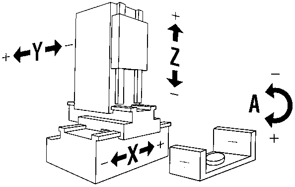
technical field [0001] The invention relates to an automobile wheel hub hole coefficient controlled milling processing device, which is used for processing the aluminum alloy automobile wheel hub hole system and belongs to the technical field of automobile manufacturing. Background technique [0002] At present, the existing CNC milling processing devices only have foreign three-axis superposition processing centers such as figure 1 As shown, the CNC milling device with this structure has low processing efficiency and low processing accuracy. [0003] The hub hole coefficient controlled milling processing device imported from abroad has a relatively complicated structure and expensive equipment. The existing processing device cannot meet the current processing needs well. Contents of the invention [0004] In order to improve the processing efficiency of the wheel hub hole coefficient and meet the requirements of high-precision machining, the present invention designs a w...

Claims


Application Information

Patent Timeline
IPC IPC(8): B23C3/00B23C1/06B23Q1/25B23Q5/40B23Q1/01B23Q7/00
Inventor 牛韬
Owner JIANGSU SLD PRECISION TECH
Learn More