Absorption tower for simultaneously removing sulfur dioxide and nitrogen oxide in smoke

A technology of sulfur dioxide and nitrogen oxides, which is applied to the absorption tower of nitrogen oxides and the field of combined removal of sulfur dioxide in flue gas, can solve the problems of reducing added value, carrying and escaping ammonia, and volatile ammonia, etc., so as to reduce the production of SO3, The effect of saving ammonia consumption and reducing system resistance

Inactive Publication Date: 2013-09-04
北京中环新锐环保技术有限公司 +2
View PDF5 Cites 17 Cited by
  • Summary
  • Abstract
  • Description
  • Claims
  • Application Information

AI Technical Summary

Problems solved by technology

[0003] The use of conventional wet desulfurization towers for simultaneous removal of sulfur and nitrate mainly has the following disadvantages: 1) usually only one absorbent is used to remove SO in flue gas 2 and NO X , the final by-product is a mixture of by-products after desulfurization and denitrification, which will cause difficulties in the separation of by-products and reduce the added value
When the desulfurization and denitrification reactions are carried out in the same absorption section, it will inevitably cause waste of absorption liquid or decrease of denitrification efficiency
3) If ammonia water is used as the absorbent, ammonia is easy to volatilize. If desulfurization and denitrification are carried out in the same absorption section, in order to ensure the denitrification efficiency, a large amount of ammonia will be carried and escaped, which will affect the utilization rate of ammonia and also affect the flue gas emission indicators

Method used


Image

  • Absorption tower for simultaneously removing sulfur dioxide and nitrogen oxide in smoke

Examples


Embodiment Construction

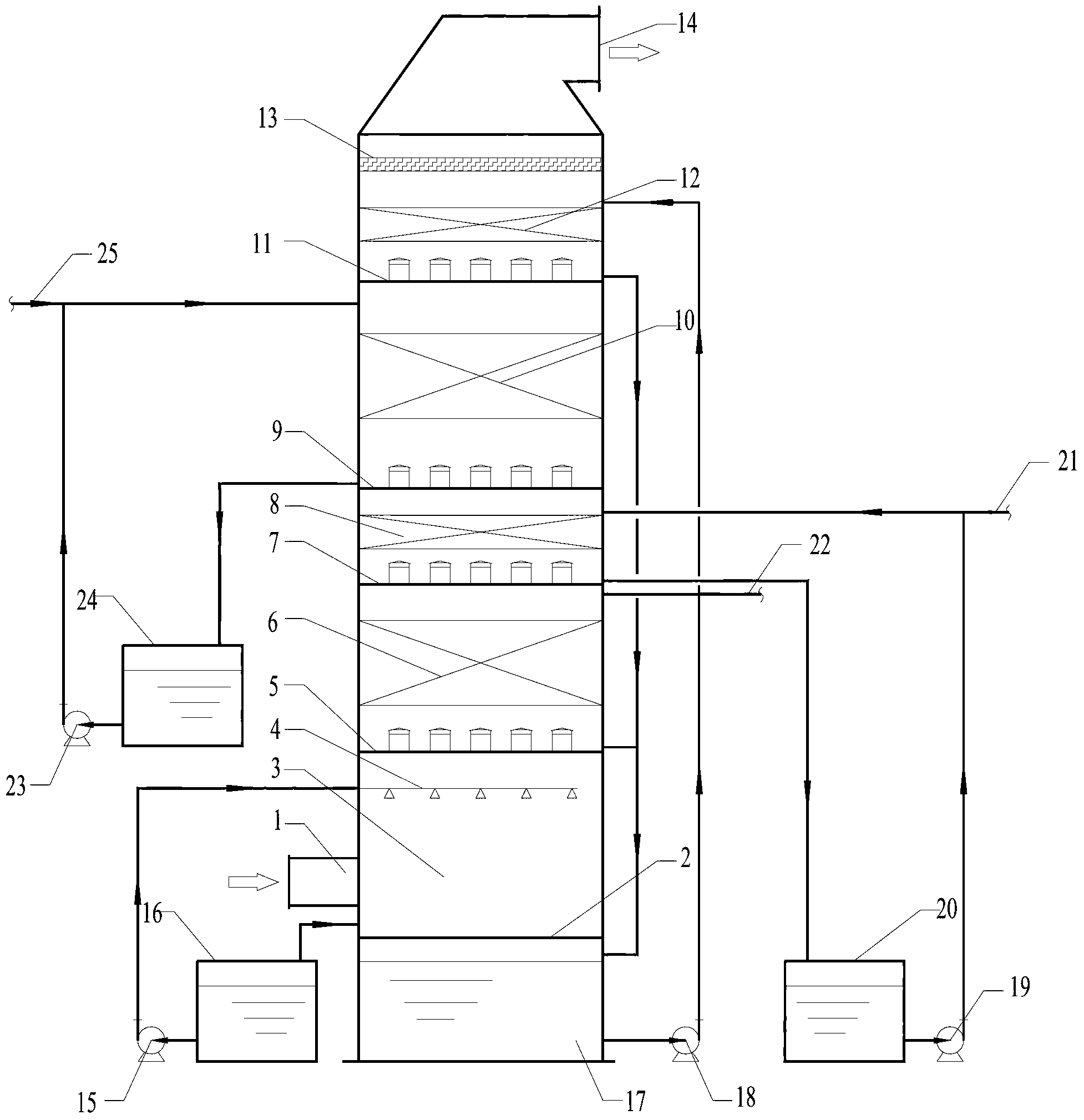
[0023] like figure 1 As shown, the interior of the absorption tower of the present invention is divided into a plurality of functional areas, and the absorption tower includes successively from bottom to top: a desulfurization absorption liquid circulation tank 17, a concentrated cooling area 3, a desulfurization absorption area 6, a flue gas conditioning area 8, Denitrification absorption area 10, ammonia escape control area 12, and mist removal area 13. When the desulfurization and denitrification absorption liquid has no volatility, the ammonia escape control zone 12 may not be set in the absorption tower.

[0024] The bottom of the absorption tower is a desulfurization absorption liquid circulation tank 17, and above it is a concentrated cooling zone 3, which is separated by a sealed tray 2, and the flue gas inlet 1 is set at the lower end of the concentrated cooling zone 3; the desulfurization absorption zone 6 is set in Above the concentration and cooling zone 3, the tw...


PUM


Abstract

An absorption tower for simultaneously removing sulfur dioxide and nitrogen oxide in smoke comprises a removed sulfur absorption liquid circulation tank, a concentration cooling area, a removed sulfur absorption area, a smoke hardening and tempering area, a removed niter absorption area, an ammonia escape control area and a demisting area, wherein the removed sulfur absorption liquid circulation tank and the concentration cooling area are isolated through a sealing tower plate; every two adjacent areas of the concentration cooling area, the removed sulfur absorption area, the smoke hardening and tempering area, the removed niter absorption area and the ammonia escape control area are separated by one tower plate provided with uniform distribution hoods; and a smoke inlet is formed in the lower end of the concentration cooling area, and a smoke outlet is formed above the demisting area. Removed sulfur and removed niter in the absorption tower can be absorbed in absorption manners such as spraying absorption, spraying and filling absorption, tower plate type absorption, and the like, and the absorption manners can be conveniently combined; a smoke hardening and tempering device can perform hardening and tempering in a gas state manner or a liquid state manner; and with the adoption of acid characteristics of a removed sulfur absorption liquid, the escape of ammonia in the denitration smoke is controlled. The absorption tower integrates multiple functions, so that system energy consumption is reduced.

Description

technical field [0001] The invention relates to an absorption tower for combined removal of sulfur dioxide and nitrogen oxides in flue gas, belonging to the technical field of air pollution control. Background technique [0002] At present, domestic wet denitrification processes are mostly based on wet desulfurization. Before the flue gas enters the absorption tower or in the absorption tower, a gaseous or liquid oxidant is added to the flue gas to oxidize NO into NO 2 , and then use alkaline absorption solution to remove NO X ; or add NO to the flue gas 2 Make NO / NO in flue gas 2 Around 1, NO and NO 2 After the combination reaction, it reacts with the alkaline absorption liquid to form nitrate, and the NO in the flue gas X was removed. This process generally uses the wet desulfurization absorption tower as the absorption tower for simultaneous removal of sulfur and nitrate, and the SO in the flue gas 2 and NO X It is removed in the same absorption section. [0003] ...

Claims


Application Information

Patent Timeline
Patent Type & Authority Applications(China)
IPC IPC(8): B01D53/78B01D53/50B01D53/56
Inventor 朱金伟王洪昌张凡王凡刘宇
Owner 北京中环新锐环保技术有限公司
Why Eureka
Try Eureka