
Electric induction assembly, stacking assembly, electric power transmission device assembly, electric measuring device assembly and single-phase electric measuring device

An electrical measurement and inductive technology, applied in the measurement of electrical variables, transformer/inductor coils/windings/connections, inductors, etc., can solve the problems of large internal space design, bulky cost of energy meters, etc.

Active Publication Date: 2013-08-28
WAHLAP TECH CO LTD
View PDF6 Cites 2 Cited by
  • Summary
  • Abstract
  • Description
  • Claims
  • Application Information

AI Technical Summary

Problems solved by technology

Therefore, in terms of structure, this requires a large internal space design to meet heat dissipation, drainage and electrical isolation. On the other hand, in order to continuously improve the functions of the electric energy meter itself, it is necessary to further improve or add other devices inside. , may require multiple boards to implement, making the energy meter bulky and costly

Method used


Image

  • Electric induction assembly, stacking assembly, electric power transmission device assembly, electric measuring device assembly and single-phase electric measuring device
  • Electric induction assembly, stacking assembly, electric power transmission device assembly, electric measuring device assembly and single-phase electric measuring device
  • Electric induction assembly, stacking assembly, electric power transmission device assembly, electric measuring device assembly and single-phase electric measuring device

Examples


Embodiment 1

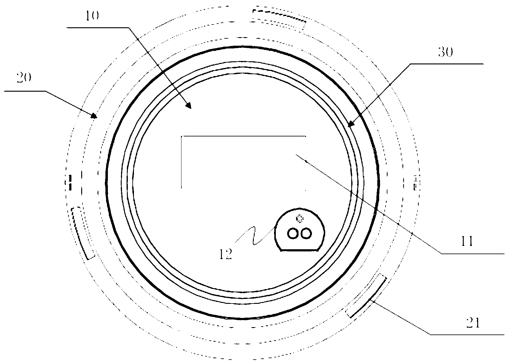
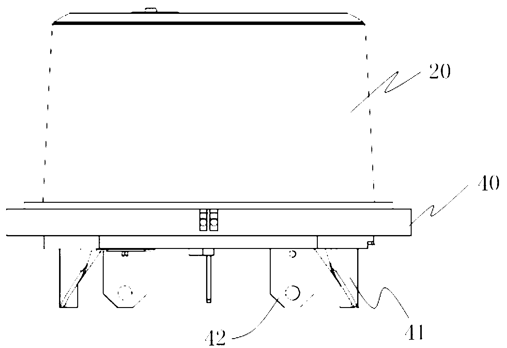
[0062] refer to figure 1 and figure 2 , figure 1 Schematically depicts the front view of the body of the electric measuring device (preferably an electric energy meter conforming to the IEC62056 protocol or the IEC61850 protocol) of the present invention, figure 2 drawn according to figure 1 A side view of the ontology. The technicians understand that the main body of the electric energy meter is roughly a cylinder or a conical frustum, and its side view is represented by the most representative angle of view. A preferred embodiment of the electrical measuring equipment assembly of the present invention includes:

[0063] Electricity measuring component, used for measuring power consumption information of the power system; transceiver component, used for communication with external power consumption information collection equipment through wireless network; front panel 10, used for displaying power consumption information of power grid; and shell 20 , for enclosing the ...

Embodiment 2

[0080] refer to figure 2 and Figure 4 , the present invention discloses a preferred embodiment of a single-phase electric measuring device, combined with reference to Figure 4 Compared with the conventional IEC statute electric energy meter or similar electric meter that complies with the statute, the improved design of the three-dimensional general diagram drawn in , includes:

[0081] circuit board (not shown in the figure), preferably installed in the figure 2 In the shown base 40, it includes an electrical measurement component for measuring power consumption information of an AC power system; a transceiver component for communicating with external power consumption information collection equipment through a wireless network; and a transformer component for connecting the contact terminals to step down said voltage and current;

[0082] The contact terminal 42 is used to connect the power line of the AC power system to obtain the AC signal of the voltage and current...


PUM

PropertyMeasurementUnit
lengthaaaaaaaaaa
widthaaaaaaaaaa
lengthaaaaaaaaaa

Abstract

The invention discloses an electric measuring device assembly, which comprises an electric measuring assembly, a front panel, a shell, a receiver-transmitter assembly, a stacking assembly and a magnetic coupling antenna assembly, wherein the auxiliary winding of the stacking assembly is respectively electrically connected to the electric measuring assembly and the receive-transmitter assembly, the magnetic coupling antenna assembly is arranged between the inside of the shell and the front panel, the electric measuring assembly is electrically isolated from the receiver-transmitter assembly, and the receiver-transmitter assembly is respectively electrically connected with the magnetic coupling antenna assembly and the electric measuring assembly. The electric induction assembly is low in cost, high in efficiency and simple and attractive in a dismounting structure, the electromagnetic interference among the electric assemblies can be greatly alleviated, and the transmission efficiency of an antenna can be optimized. The invention also discloses an electric induction assembly, a stacking assembly and an electric power transmission device assembly, involved in the electric measuring device assembly. The invention also discloses a single-phase electric measuring device.

Description

technical field [0001] The invention relates to a power system electrical measuring device with multiple functions and its power components. More specifically, the embodiment of the invention discloses a single-phase electrical measuring instrument. Background technique [0002] Conventional electrical measuring equipment, such as electric energy meters, are all rectangular in structure. Designers design the internal structure based on the shell as a frame, that is, lead wires are connected in or out through terminal buttons. At the same time, a plurality of transformers will be set at the acquisition end to transform the AC signal collected by the end button to obtain a voltage signal that can be analyzed by the data processing circuit. Therefore, in terms of structure, this requires a large internal space design to meet heat dissipation, drainage and electrical isolation. On the other hand, in order to continuously improve the functions of the electric energy meter itself,...

Claims


Application Information

Patent Timeline
Patent Type & Authority Applications(China)
IPC IPC(8): H01F38/14H01F27/28G01R11/00
Inventor 钱海波徐鹤还陈亚男
Owner WAHLAP TECH CO LTD
Learn More