
A method of processing a motor housing

A processing method and motor housing technology, applied in the field of mechanical processing, can solve the problems of motor insufficiency, motor wear, affecting the quality and life of the motor, etc., and achieve the effects of reducing wear, reducing the repair rate and prolonging the service life.

Active Publication Date: 2015-11-04
CSR ZHUZHOU ELECTRIC LOCOMOTIVE RES INST
View PDF6 Cites 0 Cited by
  • Summary
  • Abstract
  • Description
  • Claims
  • Application Information

AI Technical Summary

Problems solved by technology

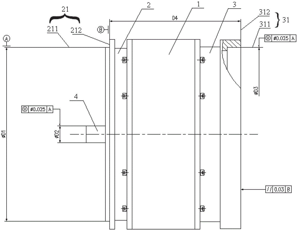
However, the machining error of each component and the cumulative error caused by the secondary clamping make the assembled motor unable to meet the above requirements. figure 1 Dimensional and geometric tolerance requirements shown in
This will cause the motor assembled from the above motor housing to be unable to be connected to the outside, or the motor will wear out during operation after the connection, which will seriously affect the quality and life of the motor

Method used


Image

  • A method of processing a motor housing
  • A method of processing a motor housing
  • A method of processing a motor housing

Examples


no. 2 Embodiment approach

[0039] It should be noted that the processing method provided by the present invention can also be completed through the second specific embodiment, and its beneficial effect is the same as that of the first specific embodiment, so it will not be repeated here. The second embodiment includes the following steps:

[0040] S100′) Preprocessing the center hole 11 of the machine base 1;

[0041] S200') Fix the base 1 and the rear end cover 3, process the inner circle 311 of the first notch with the axis of the central hole 11 as the reference, and process the end face 312 of the first notch with the end face of the support 1 as the reference;

[0042] S300') then connect the base 1 and the front end cover 2, and process the outer circle 211 of the first convex stop, the bearing installation hole 22 of the front end cover and the bearing installation hole 32 of the rear end cover with the axis of the inner circle 311 of the first concave stop as the reference. , process the first co...


PUM


Abstract

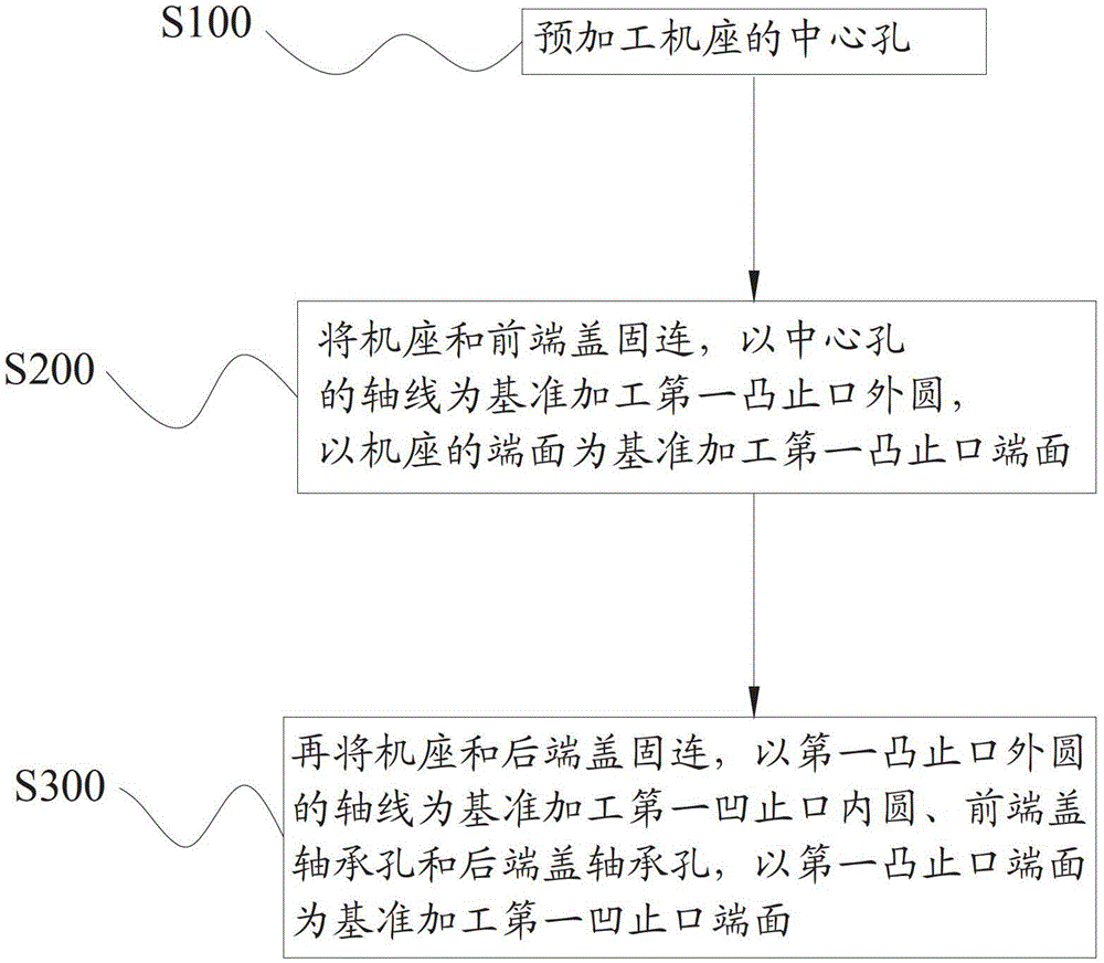
The invention discloses a manufacturing method for a motor shell body. The method includes the flowing steps: S100, pre-machining a central hole of a motor base; S200, fixedly connecting the motor base with either end cover, taking the axis of the central hole as a standard to machine a circle of an externally connected stopping opening of the fixedly connected end cover, and taking the end face of the motor base as a standard to machine an externally connected stopping opening end face of the externally connected stopping opening of the end cover; S300, fixedly connecting the motor base with the other end cover, taking the axis of the machined circle of the externally connected stopping opening as a standard to machine bearing installation holes of two end covers and a circle of an externally connected stopping opening of the other end cover, and taking the machined end face of the externally connected stopping opening as a standard to machine an end face of the externally connected stopping opening of the other end cover. Compared with the prior art, the manufacturing method for the motor shell body enables the motor shell body to have a high-precision form and location tolerance, an assembled motor can still meet requirements of the high-precision size and the shape position tolerance even under the condition that assembling errors exist in an accumulated assembling process, the repairing rate of the motor shell body is reduced, abrasion of a motor in the running process is reduced, and the service life of the motor is prolonged.

Description

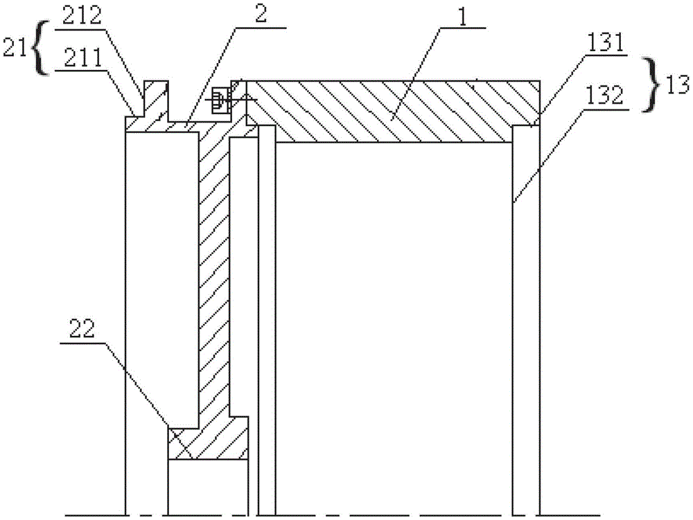
technical field [0001] The invention relates to the technical field of mechanical processing, in particular to a processing method for a motor casing. Background technique [0002] Such as figure 1 as shown, figure 1 A schematic structural view of a split motor is shown. The split motor includes a motor casing, a stator winding and a rotor arranged in a frame, wherein the motor casing includes a frame 1 and a motor that is fixedly connected to the frame 1. The front end cover 2 and the rear end cover 3, wherein, the front end cover 2 and the rear end cover 3 both have an external seam and a bearing installation hole. [0003] Compared with traditional motors, in actual use, this type of motor is connected to the outside through the external joints on the front and rear end covers. In order to ensure the normal operation of the motor after assembly, this type of motor still needs to meet high-precision size and shape requirements after assembly. bit tolerance requirements....

Claims


Application Information

Patent Timeline
Patent Type & Authority Patents(China)
IPC IPC(8): H02K15/14
Inventor 冯江华罗英露邹煜林李益丰胡勇峰王征宇黄德聪辛本雨元约平陈致初史文波
Owner CSR ZHUZHOU ELECTRIC LOCOMOTIVE RES INST
Learn More