
Long working distance microscopic optical system for vacuum chamber inner observation

A technology of working distance and optical system, applied in optics, microscopes, optical components, etc., can solve the problem of not being able to observe small objects from a distance, and achieve the effect of ensuring energy passing rate, reasonable distribution of optical power, and increasing front working distance.

Inactive Publication Date: 2015-04-22
CHANGCHUN INST OF OPTICS FINE MECHANICS & PHYSICS CHINESE ACAD OF SCI
View PDF4 Cites 2 Cited by
  • Summary
  • Abstract
  • Description
  • Claims
  • Application Information

AI Technical Summary

Problems solved by technology

[0006] In order to solve the problem that the existing miniaturized and long working distance micro-optical system suitable for space applications cannot carry out long-distance observation of tiny targets in the vacuum cavity, the present invention provides a long working distance for observation in the vacuum cavity Microscopic optical system, which increases the front working distance and realizes the observation of tiny targets in the vacuum cavity

Method used


Image

  • Long working distance microscopic optical system for vacuum chamber inner observation
  • Long working distance microscopic optical system for vacuum chamber inner observation
  • Long working distance microscopic optical system for vacuum chamber inner observation

Examples


Embodiment Construction

[0021] The present invention will be described in further detail below in conjunction with the accompanying drawings.

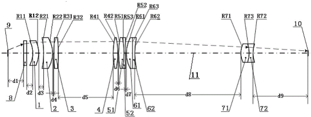
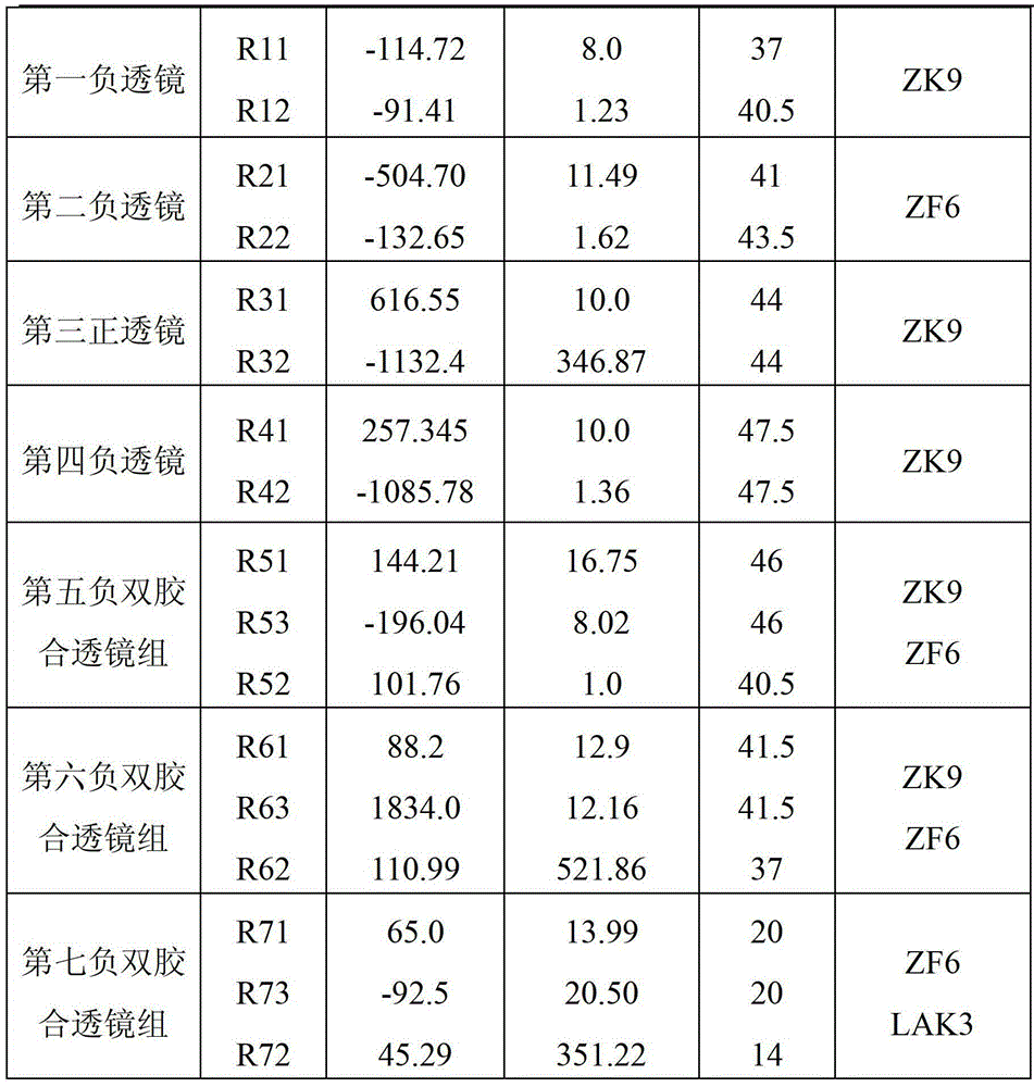
[0022] Such as figure 1 As shown, the long working distance micro-optical system for observation in the vacuum chamber of the present invention, from the object plane 9 to the image plane 10, is arranged in sequence along the optical axis 11: a window glass 8, a front lens group, and a middle lens group And the rear lens group, the front lens group is composed of the first negative lens 1, the second negative lens 2 and the third positive lens 3; the middle lens group is composed of the fourth negative lens 4, the fifth negative doublet lens group 5 and the sixth negative lens group The doublet lens group 6 is formed, the fifth negative doublet lens group 5 is made up of the fifth positive lens 51 and the fifth negative lens 52, and the sixth negative doublet lens group 6 is made up of the sixth positive lens 61 and the sixth negative lens 62 The rear lens g...


PUM


Abstract

The invention provides a long working distance microscopic optical system for vacuum chamber inner observation and relates to the field of optical design. The long working distance microscopic optical system for the vacuum chamber inner observation solves the problem that an existing small-scaled long working distance microscopic optical system suitable for space application can not conduct observation on a small object in a vacuum chamber. Window glass, a first concave lens, a second concave lens, a third convex lens, a fourth concave lens, a fifth convex lens, a fifth concave lens, a sixth convex lens, a sixth concave lens, a seventh convex lens and a seventh concave lens are sequentially arranged on the optical system from an object plane to an image plane along an optical axis. The distance d1 between the object plane and the window glass is 98mm. Light beams from the object plane sequentially pass through the window glass, the first concave lens, the second concave lens, the third convex lens, the fourth concave lens, the fifth convex lens, the fifth concave lens, the sixth convex lens, the sixth concave lens, the seventh convex lens and the seventh concave lens to the image plane. The long working distance microscopic optical system for the vacuum chamber inner observation lengthens the front working distance to 98mm, the small object in the vacuum chamber can be observed at a long distance, and chromatic aberration is corrected.

Description

technical field [0001] The invention relates to the technical field of optical design, in particular to a long working distance micro-optical system for observation in a vacuum cavity. Background technique [0002] With the continuous improvement of the coverage and spatial resolution requirements of space remote sensors in many fields such as resource census and military reconnaissance, the demand for the development of space cameras with large fields of view and long focal lengths is becoming increasingly urgent. An important direction for the development of space remote sensors. [0003] In the process of developing a long focal length space camera, it is necessary to test the adaptability of the structure of the space camera to the space environment, such as the deformation of the support structure of the space camera in a thermal vacuum environment and the vacuum deflation deformation characteristics of carbon fiber materials. To observe the amount of deformation, a mi...

Claims


Application Information

Patent Timeline
Patent Type & Authority Patents(China)
IPC IPC(8): G02B21/02G02B13/00G02B1/00
Inventor 张元金光钟兴刘春雨王天聪孔令胜
Owner CHANGCHUN INST OF OPTICS FINE MECHANICS & PHYSICS CHINESE ACAD OF SCI
Learn More