
A control method and control system for furnace negative pressure in a thermal power plant

A furnace negative pressure and control system technology, which is applied in the combustion method, control combustion, lighting and heating equipment, etc., can solve the problems of PID unable to complete stable negative pressure, accelerated furnace pressure drop trend, RB function failure, etc., to prevent furnace The pressure exceeds the lower limit, eliminates negative effects, and prevents the effect of furnace pressure exceeding the limit

Active Publication Date: 2015-11-11
STATE GRID CORP OF CHINA +2
View PDF6 Cites 0 Cited by
  • Summary
  • Abstract
  • Description
  • Claims
  • Application Information

AI Technical Summary

Problems solved by technology

The parameters in the conventional PID are suitable for normal operating conditions. When the primary fan is RB, problems are likely to occur: the adjustment is slow, which will lead to an accelerated downward trend of the furnace pressure, and the trip of the unit will occur if the lower limit is exceeded.
Parameter adjustment causes the stator blade of the induced draft fan to overshoot, which will cause the pressure to rise too fast, and the unit will trip if it exceeds the upper limit
Conventional PID often cannot complete the task of stabilizing the negative pressure, and the negative pressure exceeds the limit, resulting in serious consequences of RB function failure and unit tripping

Method used


Image

  • A control method and control system for furnace negative pressure in a thermal power plant
  • A control method and control system for furnace negative pressure in a thermal power plant

Examples


Embodiment Construction

[0020] The present invention will be described in detail below in conjunction with the accompanying drawings.

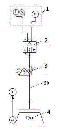
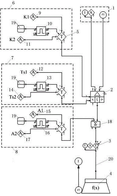
[0021] The control system of the furnace negative pressure of the thermal power plant of the present invention is as figure 1 As shown, it includes a control panel 1 , a PID regulator 2 , an adder 18 , an ID fan vane M / A station 3 and an ID fan vane output 4 . The control panel is connected with the PID regulator circuit, and the PID regulator is connected with the induced fan stator blade control output single-loop circuit 20 through the M / A station of the induced draft fan stator and the adder 18 . The variable proportional coefficient unit 6 is provided with a proportional coefficient constant module 9 , a proportional coefficient switching pulse module 10 , a variable proportional coefficient constant module 11 , a switch input module 19 and a switching module 5 . The switch input module is connected with the proportional coefficient switching pulse module. The...


PUM


Abstract

The invention relates to a method and a system for controlling negative pressure of furnace hearths of a thermal power plant. The controlling system comprises a control panel, a PID (proportion, integration and differentiation) adjustor, a summator, a proportion coefficient changing unit, an integration time changing unit, a primary fan RB (runback) feedforward unit, an induced draft fan stationary blade M / A station and an induced draft fan stationary blade control output end, the proportion coefficient changing unit and the integration time changing unit are respectively connected with the PID adjustor, and the primary fan RB feedforward unit is connected with a single loop circuit through the summator. By adding a parameter changing function to the controlling system and primary fan RB feedforward, when primary fan RB occurs, a proportion coefficient is increased, so that response speed of the adjustor to deviation amplitude is increased, integration time is increased, integral action is reduced, and adverse impact brought by lag of integral adjusting is eliminated. When the primary fan RB occurs, an induced draft fan stator blade is quickly closed through feedforward, so that the problem that overpressure of the furnace hearths during the primary fan RB is effectively prevented, and pressure control level of the furnace hearths and operating safety of thermal power unit are improved.

Description

technical field [0001] The invention belongs to the technical field of production process control, and relates to a control method and a control system for furnace negative pressure in a thermal power plant. Background technique [0002] Furnace negative pressure is an important parameter for the operation of thermal power plants, and the furnace negative pressure control system is one of the important control systems of thermal power plants, which involves the safety of unit operation. If the furnace negative pressure exceeds the protection setting value, it will cause the unit to trip, and in severe cases, it will damage the boiler equipment and affect the personal safety of production operators. [0003] The control of furnace negative pressure is generally adjusted by induced draft fan (the common ones are baffle adjustment, stationary blade adjustment or frequency conversion adjustment, the three principles are the same), and the control method is a conventional single-...

Claims


Application Information

Patent Timeline
Patent Type & Authority Patents(China)
IPC IPC(8): F23N3/00
Inventor 张洪涛彭钢刘永红饶群王艳侯双林李士林
Owner STATE GRID CORP OF CHINA
Learn More