
Seal structure for fuel cell

A technology of fuel cell and sealing structure, applied in the field of sealing structure, to achieve the effect of easy component shape, manufacturing and assembly

Inactive Publication Date: 2013-08-14
NOK CORP
View PDF9 Cites 2 Cited by
  • Summary
  • Abstract
  • Description
  • Claims
  • Application Information

AI Technical Summary

Problems solved by technology

[0003] Recently, in order to promote the popularization of fuel cells, the simplification of the shape of parts, the simplification of manufacturing and assembly, and the reduction of cost have been achieved. or the liner is integrally formed, so there are still problems to be solved

Method used


Image

  • Seal structure for fuel cell
  • Seal structure for fuel cell
  • Seal structure for fuel cell

Examples


Embodiment

[0068] Next, embodiments of the present invention will be described with reference to the drawings.

no. 1 example

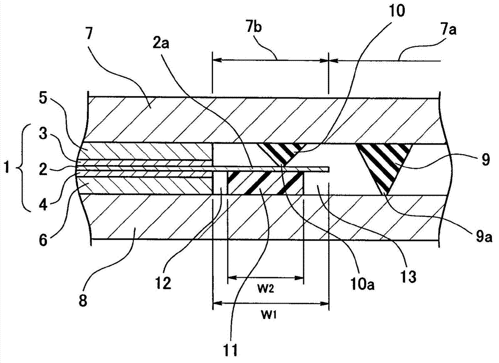
[0070] figure 1 A main part cross-section of the fuel cell sealing structure according to the first embodiment of the present invention is shown, and the sealing structure is configured as follows.

[0071] That is, first, as a basic configuration, a membrane electrode assembly (MEA) 1 in which a pair of (anode side and cathode side) electrode layers 3 and 4 are provided on both sides of the electrolyte membrane 2 in the thickness direction is provided. 1 is sandwiched by a pair of separation devices 7, 8 via a pair of gas diffusion layers (GDL) 5, 6. As the relationship between the dimensions of these fuel cell components, the planar dimensions of the pair of electrode layers 3, 4 and the pair of gas diffusion layers 5, 6 are set to be the same as each other, and the planar dimensions of the electrolyte membrane 2 are set to be larger than those of the electrode layers. 3 and 4 and the gas diffusion layers 5 and 6 have large planar dimensions, and the planar dimensions of t...

no. 4 example

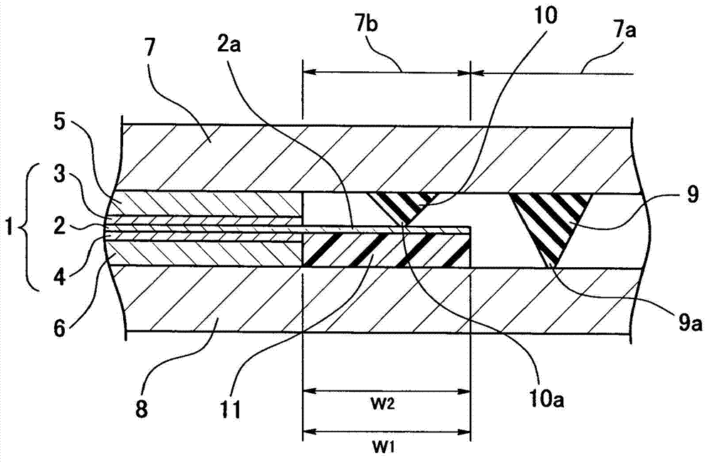
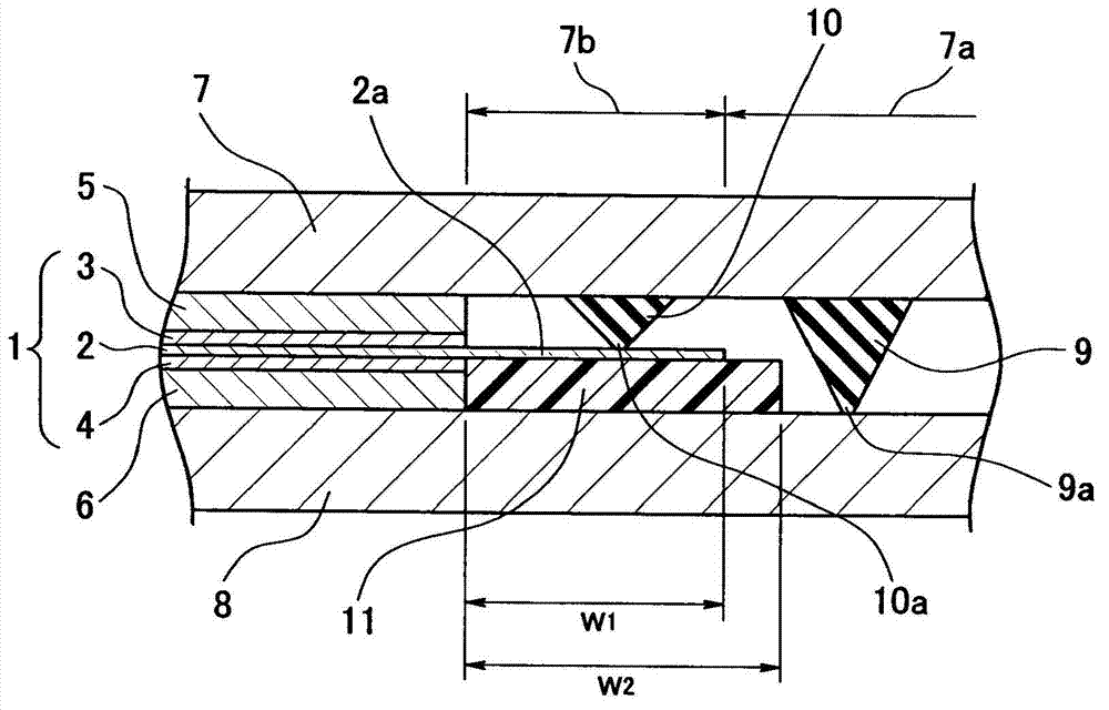
[0083] Figure 4 A cross section of a main part of a fuel cell sealing structure according to a fourth embodiment of the present invention is shown, and the sealing structure is configured as follows.

[0084] That is, first, as a basic configuration, a membrane electrode assembly (MEA) 1 in which a pair of (anode side and cathode side) electrode layers 3 and 4 are provided on both sides of the electrolyte membrane 2 in the thickness direction is provided. 1 is sandwiched by a pair of separation devices 7, 8 via a pair of gas diffusion layers (GDL) 5, 6. As the relationship between the dimensions of these fuel cell components, the planar dimensions of the pair of electrode layers 3, 4 and the pair of gas diffusion layers 5, 6 are set to be the same as each other, and the planar dimensions of the electrolyte membrane 2 are set to be larger than those of the electrode layers. 3 and 4 and the gas diffusion layers 5 and 6 have large planar dimensions, and the planar dimensions of...


PUM


Abstract

Provided is a fuel cell seal structure that can achieve simplification of component shapes, easier production and assembly, and cost reductions because groove processing in one of a pair of separators sandwiching a membrane electrode assembly and integral forming of gaskets are unnecessary. To achieve this purpose, a membrane electrode assembly provided with electrode layers on both sides of an electrolyte membrane and separators that sandwich the membrane electrode assembly are provided. The planar dimensions of the electrode layers are set identical to each other. The planar dimensions of the electrolyte membrane are set larger than the electrode layers. The planar dimensions of the separators are set even larger than the electrolyte membrane. Based on this basic constitution, a first gasket held by one separator and in intimate contact with the other separator and a second gasket held by the one separator and in intimate contact with the electrolyte membrane are provided. Also provided is a reinforcing member that is separate from the electrode layer and that is meant to reinforce the electrolyte membrane with which the second gasket is in intimate contact from the back surface of the electrolyte membrane.

Description

technical field [0001] The present invention relates to a sealing structure of a fuel cell. Background technique [0002] previously as Figure 9 As shown, there is known a fuel cell having a membrane electrode assembly 51 provided with a pair of electrode layers 53, 54 on both sides of an electrolyte membrane 52, and the membrane electrode assembly 51 is sandwiched by a pair of separators 55, 56. battery (refer to Patent Document 1). In addition, in this fuel cell, in order to seal fluids such as combustible gas, gaskets 57 and 58 are respectively attached to the anode side and the cathode side on the peripheral portion of the membrane electrode assembly 51. Figure 9 In the example, grooves 55a, 56a are respectively provided at corresponding positions of a pair of separation devices 55, 56, liners 57, 58 are installed in each grooves 55a, 56a, and each liner 57, 58 is connected to the electrolyte membrane 52 Close contact. In addition, there are cases where the gaskets 5...

Claims


Application Information

Patent Timeline
IPC IPC(8): H01M8/02H01M8/10
CPCH01M8/10H01M8/0271H01M2008/1095Y02E60/521H01M2/08H01M8/02H01M8/0276Y02E60/50Y02P70/50H01M8/0267H01M8/0273
Inventor 古贺正太郎藏野庆宏
Owner NOK CORP
Learn More