
Improved noise reduction control for wind turbines

A wind turbine and noise technology, which is applied in the field of improved noise reduction control for wind turbines, can solve the problems of wind turbine reduction cost-effectiveness, and achieve the effect of accurate prediction

Active Publication Date: 2013-08-14
SIEMENS GAMESA RENEWABLE ENERGY AS
View PDF5 Cites 19 Cited by
  • Summary
  • Abstract
  • Description
  • Claims
  • Application Information

AI Technical Summary

Problems solved by technology

The reduced cost-effectiveness of wind turbines makes such a solution undesirable

Method used


Image

  • Improved noise reduction control for wind turbines
  • Improved noise reduction control for wind turbines
  • Improved noise reduction control for wind turbines

Examples


Embodiment Construction

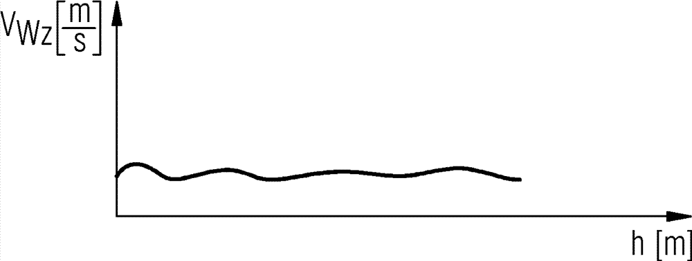
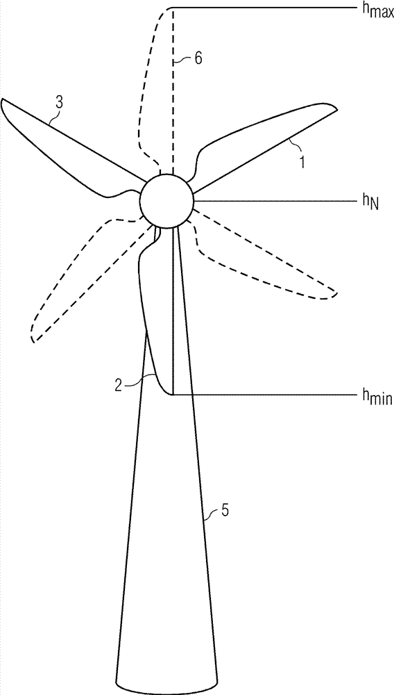
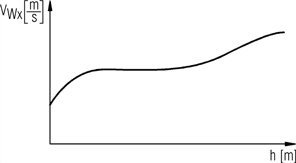
[0028] figure 1 shows the wind velocity v as a function of height h w the first graph of . This wind speed profile is merely exemplary in nature and relates only to real examples where the wind speed is typically lower at lower altitudes above ground than at higher altitudes.

[0029] In this graph, h N represents the height of the nacelle of the wind turbine, and h min and h max Indicates the minimum and maximum heights of the rotor blade tips. As can be seen from this graph, the force applied to the rotor blades will vary greatly with rotor azimuth because of the difference in wind speed at different heights. Different wind speeds also mean that the noise emission will vary depending on the rotor azimuth. If the rotor blade pitches with a low noise emission at one rotor azimuth, the selected pitch may not be suitable for a different rotor azimuth and cause an unnecessary amount of noise for a second rotor azimuth. This is because the wind speed increases with the min...


PUM


Abstract

The invention provides a method of controlling noise emission from a wind turbine comprising at least one rotor blade (1, 2, 3). The inventive method comprises steps of: Providing wind shear data comprising wind shear values as a function of height over ground; Determining an expected noise emission based on the wind shear data; and Controlling the wind turbine to reduce noise emission from the wind turbine in accordance with the expected noise emission.

Description

Background technique [0001] As more and more wind farms are built, wind turbines move closer to densely populated areas. Consequently, the impact of acoustic emissions caused by such wind power plants on nearby populations will become an increasingly important issue. The implementation of a closed loop noise control function is difficult because the sound level will be affected not only by the noise generated by the wind turbine but also by any other sound sources in the vicinity of the plant being built. Therefore, limitations on sound emissions based on noise level or noise spectrum measurements would be unrealistic. Therefore, known solutions typically involve defining a number of operating modes in which a compromise between optimal power generation performance and acceptable noise level has been reached. In other words, the power output of the wind turbine can be reduced due to reduced noise emissions. The reduced cost-effectiveness of wind turbines makes such a soluti...

Claims


Application Information

Patent Timeline
Patent Type & Authority Applications(China)
IPC IPC(8): F03D7/04
CPCY02E10/723F05B2270/321F05B2260/96F03D11/00F05B2270/32F05B2270/331F05B2270/326F03D7/0296F05B2270/333F03D80/00Y02E10/72
Inventor K.S.尼尔森
Owner SIEMENS GAMESA RENEWABLE ENERGY AS
Learn More