
Foam-assisted hydraulic sandblasting perforating technique pipe string and method

A technique of pipe string and sandblasting perforation, which is applied in the direction of earthwork drilling, production fluid, wellbore/well components, etc. It can solve the problems of poor sand carrying capacity, increased perforation depth, liquid infiltration, etc., and achieves improved carrying capacity. sand capacity, reducing the penetration into the formation, and reducing the effect of confining pressure

Active Publication Date: 2013-08-14
PETROCHINA CO LTD
View PDF8 Cites 7 Cited by
  • Summary
  • Abstract
  • Description
  • Claims
  • Application Information

AI Technical Summary

Problems solved by technology

Existing hydraulic sandblasting perforation technologies, such as those involved in Chinese patent CN101539007A and Chinese patent CN2580110Y, do not increase the perforation depth by reducing the wellbore fluid column pressure
On the other hand, due to the poor sand-carrying ability of the liquid, a large amount of sprayed abrasives and broken rock chips accumulate around the nozzle, preventing the abrasive slurry from being sprayed onto the formation, consuming the impact energy of the abrasive slurry, and seriously affecting the injection rate. Depth of sand perforation
In addition, the wellbore fluid column pressure is usually greater than the formation pressure. During the perforation process, a large amount of liquid will seep into the reservoir and cause damage to the reservoir

Method used


Image

  • Foam-assisted hydraulic sandblasting perforating technique pipe string and method

Examples


Embodiment Construction

[0024] In order to have a clearer understanding of the technical features, purposes and effects of the present invention, the specific implementation manners of the present invention will now be described with reference to the accompanying drawings.

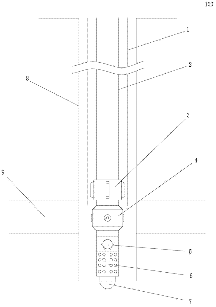
[0025] Such as figure 1 As shown, the present invention proposes a foam-assisted hydraulic sand blasting perforation process string 100, the process string 100 includes an outer oil pipe 1 lowered into the wellbore 8 and a sandblasting pipe installed in the outer oil pipe 1 column; the sand blasting string is composed of inner oil pipe 2, centralizer 3, hydraulic injector 4, one-way valve 5, screen pipe 6 and plug 7 in order from top to bottom; the hydraulic injector 4 is located in the oil layer 9; the total length of the inner oil pipe 2 is 1-2m shorter than the total length of the outer oil pipe 1, so as to ensure that the inner oil pipe 2 and the centralizer 3 are located inside the outer oil pipe 1, while the hydraulic injec...


PUM


Abstract

The invention relates to a foam-assisted hydraulic sandblasting perforating technique pipe string and a method. The technique pipe string comprises an outer oil pipe tripping in a shaft and a sandblasting pipe string penetratingly arranged in the outer oil pipe. The sandblasting pipe string is composed of an inner oil pipe, a centering device, a hydraulic ejector, a one-way valve, a screen pipe and a plug in sequential connection form top to bottom, and the hydraulic ejector is located at a perforating position of an oil layer. A hydraulic sandblasting perforating technology and a foam sandblasting technology are combined, hydraulic sandblasting perforating is performed while foam fluid is injected from the outer oil pipe, fluid column pressure of the shaft is decreased by the aid of the foam fluid, and ambient pressure of hydraulic sandblasting perforating is decreased; sand carrying capability is improved, abrasives and debris accumulated around a nozzle of the hydraulic ejector are cleaned, and accordingly depth of perforating is increased; and further, 'negative pressure' of the shaft can be formed by the foam fluid, fluid penetrating into the formation is reduced, and damages to reservoirs during perforating are reduced.

Description

technical field [0001] The invention relates to a hydraulic sand blasting perforation technology for oil wells, in particular to a foam-assisted hydraulic sand blasting perforation process string and method. Background technique [0002] Hydraulic sandblasting perforation is a new technology that uses high-pressure sanding fluid to jet-drill oil well casings, cement sheaths and formations; since no compaction zone is produced during the perforation process, the pollution to the oil layer is reduced It is widely used in low permeability reservoirs, heavily polluted formations and pre-fracturing pretreatment. [0003] Perforation depth is one of the main indicators to measure the effect of hydraulic sandblasting perforation; and perforation depth is related to factors such as fluid pressure, sand content, sand grain properties and confining pressure; due to the limitation of equipment conditions, it is difficult to improve Fluid pressure, sand content, and changing the proper...

Claims


Application Information

Patent Timeline
Patent Type & Authority Applications(China)
IPC IPC(8): E21B43/114
Inventor 匡韶华王宝权张建军柳燕丽石磊佟姗姗于丽宏郭定雄
Owner PETROCHINA CO LTD
Learn More