
High-efficiency heating solid tire vulcanization device

A solid tire, high-efficiency technology, applied in tires, other household appliances, household appliances, etc., can solve the problems of wasting vulcanizing machine use efficiency, vulcanization degree difference, and large waste of heat energy, so as to improve the overall quality of products and reduce performance differences. , the effect of reducing heat loss

Inactive Publication Date: 2013-08-14
ZHONGCE RUBBER GRP CO LTD
View PDF2 Cites 2 Cited by
  • Summary
  • Abstract
  • Description
  • Claims
  • Application Information

AI Technical Summary

Problems solved by technology

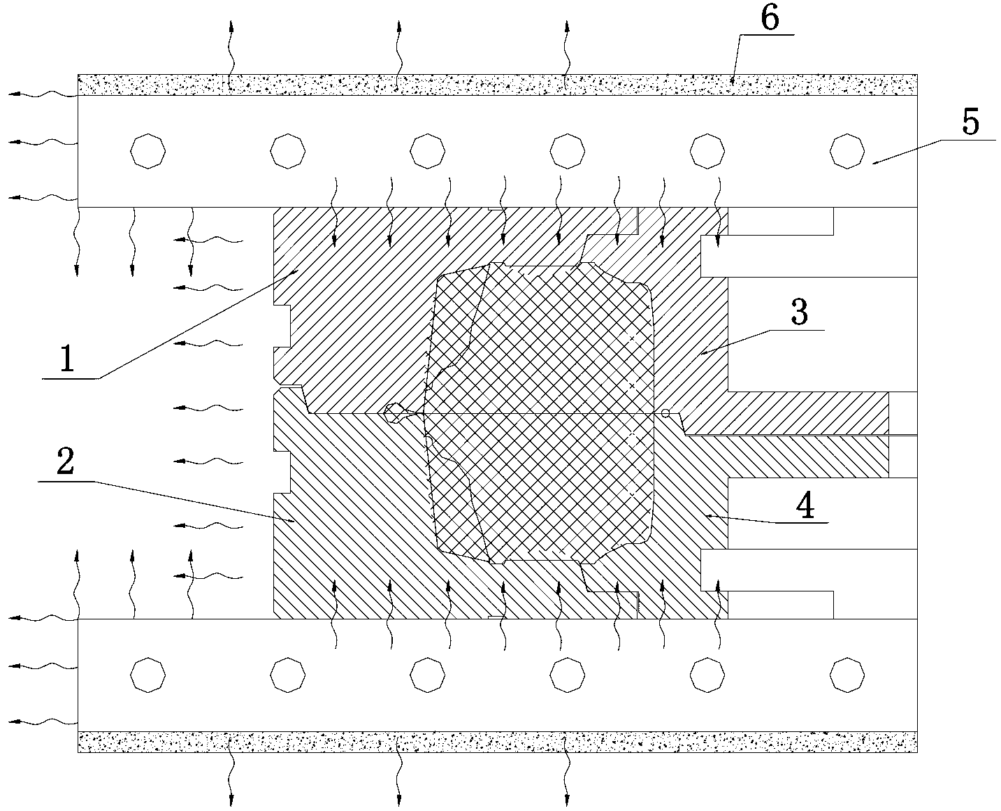
The heat medium first transfers heat to the mold through the hot plate 5, and then transfers heat from the mold to the tire in the cavity. The heat transfer distance and time are longer. At the same time, the hot plate also transfers heat to the machine and the external environment, and the longer the time The greater the waste of heat energy
In the mold preheating stage, due to the long heat transfer distance, the preheating time is long, which wastes the use efficiency of the vulcanizer
The traditional solid tire vulcanization mold has the disadvantages of low heat energy utilization rate and low production efficiency
The traditional solid tire vulcanization mold relies on the upper and lower hot plates to transfer heat, which is also unfavorable to the quality of the product. The two sides closest to the heating source reach the vulcanization point first, while the far middle part reaches the vulcanization point last. Different tires There is a large difference in the degree of vulcanization of the parts, which affects the overall quality of the tire

Method used


Image

  • High-efficiency heating solid tire vulcanization device
  • High-efficiency heating solid tire vulcanization device

Examples


Embodiment Construction

[0011] The specific implementation manner of the present invention will be described in detail below in conjunction with the accompanying drawings.

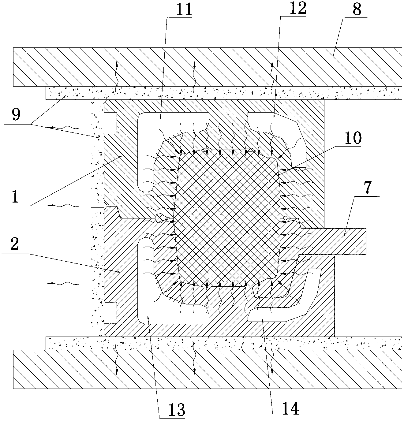
[0012] Such as figure 2 A high-efficiency heating solid tire vulcanization device is shown, the vulcanization device includes an upper mold 1 and a lower mold 2 . The mold cavity of the upper mold 1 constitutes the mold cavity 10 of the half outer surface of the solid tire, and an upper heat medium heating chamber is arranged at least along the tire tread in the upper mold 1; the upper heat medium heating chamber is divided into the left upper heat medium The heating chamber 11 and the upper right heating medium heating chamber 12, the upper left heating medium heating chamber 11 extends to the tread, shoulder and sidewall, and the upper right heating medium heating chamber 12 extends to the tread and shoulder. The right side of the lower die 2 is provided with a lower steel ring 7, the lower steel ring 7 includes an annular po...


PUM


Abstract

The invention relates to a high-efficiency heating solid tire vulcanization device which comprises an upper die and a lower die, wherein a die cavity of the upper die forms a die cavity for a half of the outer surface of a solid tire; an upper heating medium heating cavity is at least arranged in the upper die along a tire tread; a lower steel ring is arranged on the right side of the lower die and comprises an annular part; the annular part is arranged on the right side of an inner ring of the lower die; a die cavity is arranged on the left side of the inner ring of the lower die; the die cavity of the lower die and the inner surface of the lower steel ring form a die cavity for the other half of the outer surface of the solid tire; a lower heating medium heating cavity is at least arranged in the lower die along the tire tread; the upper die and the lower die are respectively fixed on a vulcanization device pressing plate; and heat isolation layers are respectively arranged between the upper die and the vulcanization device pressing plate and between the lower die and the vulcanization device pressing plate. By the high-efficiency heating solid tire vulcanization device, the heat energy utilization rate, the production efficiency and the vulcanization uniformity are improved, and thus the overall quality of products is improved.

Description

technical field [0001] The invention relates to a tire curing machine, in particular to a high-efficiency heating solid tire curing device. Background technique [0002] Existing solid tire vulcanization mold is mainly made of upper die 1, lower die 2, upper steel ring 3, lower steel ring 4 ( figure 1 ), the upper steel ring 3 is installed inside the upper mold 1, the lower steel ring 4 is installed on the central mechanism of the vulcanizer inside the lower mold 2, the upper mold 1 and the lower mold 2 are installed on the upper and lower hot plates 5 of the vulcanizer respectively, and the upper and lower A heat insulating layer 6 is provided on the outside of the hot plate 5 . When solid tire is vulcanized, the upper and lower molds 1, 2 and the upper and lower steel rings 3, 4 form the mold cavity for tire vulcanization molding, and the heat is transferred to the inside of the mold cavity by the upper and lower two hot plates 5 of the vulcanizer and the peripheral heati...

Claims


Application Information

Patent Timeline
Patent Type & Authority Applications(China)
IPC IPC(8): B29C35/02B29L30/00
Inventor 郑斌王洁王道和马鑫
Owner ZHONGCE RUBBER GRP CO LTD
Learn More