
Pet detector modules utilizing overlapped light guides

A technology of detectors and nuclear detectors, applied in radiation measurement, optical waveguide light guides, instruments, etc., can solve the problems of shared PMT strength, lengthy PMT assembly time, etc., achieve large structure and thermal stability, shorten construction time, The effect of eliminating seams

Active Publication Date: 2013-08-07
KONINKLIJKE PHILIPS ELECTRONICS NV
View PDF9 Cites 3 Cited by
  • Summary
  • Abstract
  • Description
  • Claims
  • Application Information

AI Technical Summary

Problems solved by technology

resulting in lengthy PMT assembly times
[0005] Also, the joint of shared PMT is not as strong as that of non-shared PMT, which may separate due to thermal or mechanical stress, because the shared columns are bonded to the seam between the two lightguides

Method used


Image

  • Pet detector modules utilizing overlapped light guides
  • Pet detector modules utilizing overlapped light guides
  • Pet detector modules utilizing overlapped light guides

Examples


Embodiment Construction

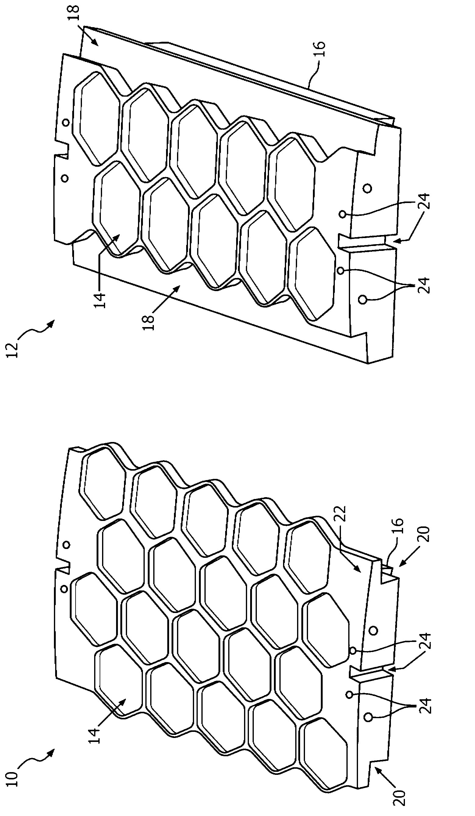
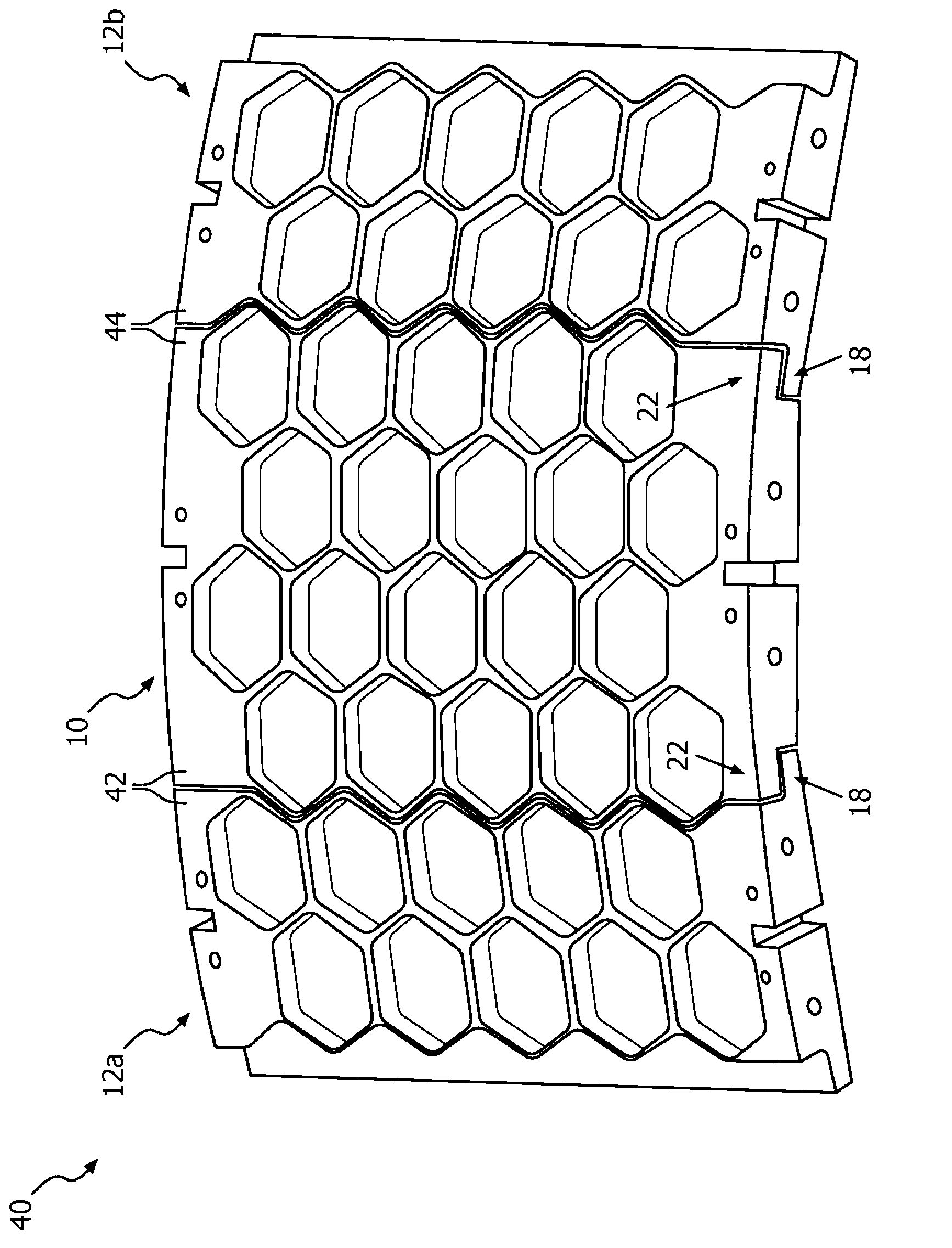
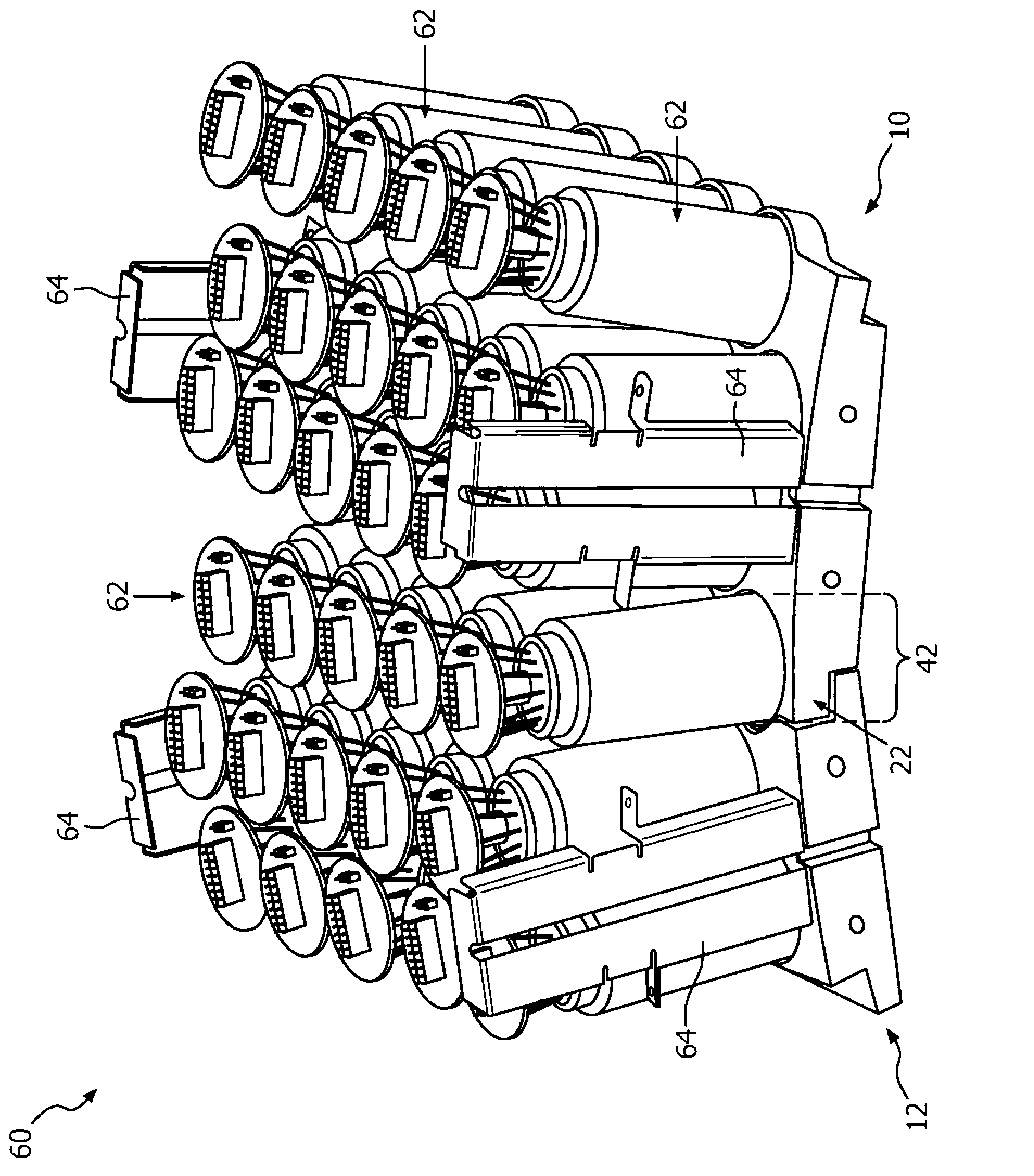
[0020] The present innovation overcomes the problems of in-situ PMT placement, and the weak bonding strength of the PMT columns shared between detector modules. The described systems and methods facilitate gluing the PMTs in place in PET detector modules prior to installation into the gantry, and grease coupling the detector modules during assembly to the gantry. Furthermore, the bonding of shared PMTs is as strong as non-shared PMT bonding, thereby overcoming the PMT disengagement problem of PMTs within a shared row.

[0021] figure 1 Shown are an upper stacked light guide 10 and a lower stacked light guide 12 that will be optically coupled together when building an array of cylindrical PMT modules for PET detectors. In the example shown, the upper stacked light guide 10 is 4 columns of light guides and the lower stacked light guide 12 is 2 columns of light guides. Each of the light guides 10, 12 has a plurality of hexagonal densely packed receptacles 14 into which a plural...


PUM


Abstract

When constructing a nuclear detector module in a gantry, a plurality of overlapping light guide modules (10) are mounted to the gantry in a spaced-apart fashion, and a plurality of underlapping light guide modules (12) are mounted in between each pair of overlapping light guide modules (10). Each of the underlapping modules and the overlapping modules includes a scintillation crystal array (16) on an interior surface thereof, and a plurality of PMTs on an exterior surface thereof. Overlapping modules (10) have overlapping structures (22) that interface with underlapping structures (18) on the underlapping modules (12) and thereby eliminate a seam directly beneath PMTs that overlap the crystal arrays of both an overlapping module and an underlapping module. Optical grease is used to form a resilient grease coupling and reduce light scatter between the underlapping and overlapping modules.

Description

technical field [0001] This application has unique application in positron emission tomography systems, and in particular relates to the construction of PET detectors and photomultiplier tube (PMT) modules in PET gantry setups. However, it should be appreciated that the described techniques may also be applied to other PMT modular construction systems, SPECT and other bench setup solutions, or other modular construction techniques. Background technique [0002] In positron emission tomography (PET) scanners, various manufacturers mount photomultiplier tubes (PMTs) and light guides to the gantry in different ways. Some modules are designed to carry several PMTs. One setup employs a single PMT and several light guide units, which results in a large number of individual installation operations. Another setup uses a cube that includes a light guide and 4 PMTs. Since the PMTs are mounted around the cylinder, the larger PMT modules must be configured to accommodate the curvatur...

Claims


Application Information

Patent Timeline
IPC IPC(8): G01T1/164G01T1/20
CPCG02B6/10G01T1/20G01T1/1644G01T1/164Y10T29/49826
Inventor T·L·劳伦斯J·刘S·E·库克S·J·普卢默
Owner KONINKLIJKE PHILIPS ELECTRONICS NV
Learn More