Wave stabilized power generation system
A power generation system, a stable technology, applied in the direction of ocean energy power generation, engines, engine components, etc., can solve the problems of small power and poor stability of a single machine, and achieve the effect of increasing power, large adaptability, and centralized power generation equipment
- Summary
- Abstract
- Description
- Claims
- Application Information
AI Technical Summary
Problems solved by technology
Method used
Image
Examples
Embodiment 1
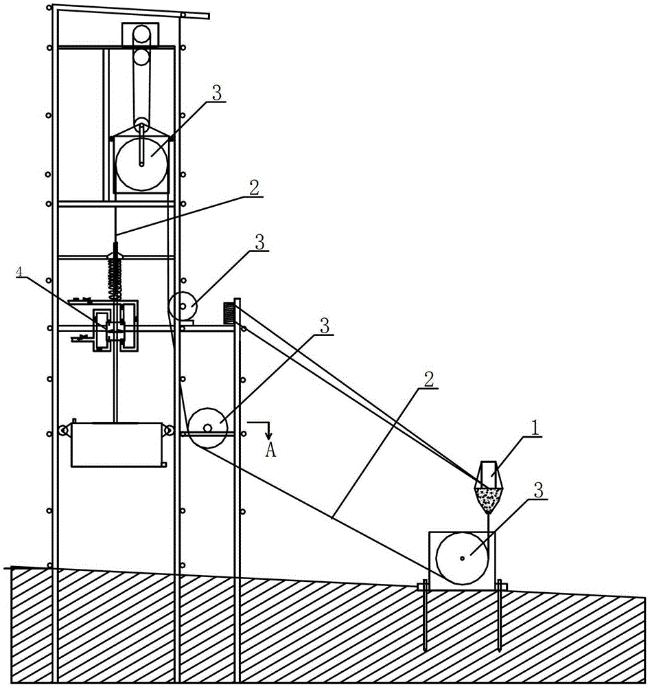
[0017] The wave energy collection unit includes a buoyant body 1, a steel rope 2, and a pulley block (for details, see "Sea Wave Power Generation System with a Floating Body Steel Rope and Rack and Flywheel Group" in application number 201210337835.7), and the buoyant body 1, steel rope 2, and the pulley block convert the energy of the sea wave The energy is converted into the energy of the reciprocating linear lifting motion. The bottom of the floating body 1 is connected to one end of the steel rope 2, and the steel rope 2 makes the other end of the steel rope move vertically through the pulley block. The other end of the steel rope 2 is connected to the upper end of the piston rod 27 of the reciprocating water pump 4 . The working direction of the piston rod 27 of the reciprocating water pump 4 is perpendicular to the horizontal plane.
[0018] The energy aggregation output system includes a confluence distributor 5, a high-pressure pipeline, a reciprocating water pump 4, ...
Embodiment 2
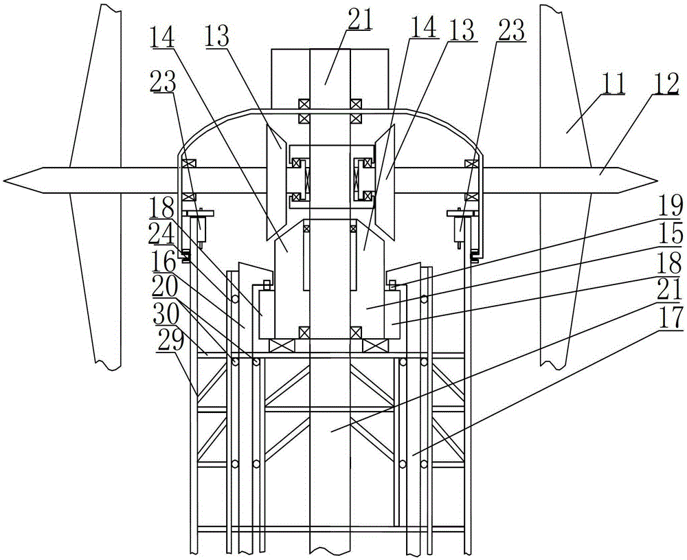
[0026] The energy collection unit of the present invention is a wind energy collection unit, and the wind energy collection unit includes a fan blade 11, a vertical main shaft 21, a horizontal turntable 15, a corbel 16, a vertical pull rod, and a tower 29, and the horizontal turntable 15 is set It is located on the top of the tower 29 and coaxially arranged with the vertical main shaft 21; the horizontal turntable 15 is driven by the wind blade 11 to rotate, and the shape of the corbel 16 is like a driving column in an upside-down industrial factory building, and it includes protruding part and pole, its protruding part is located above the outer edge of the horizontal turntable 15, the pole part of the corbel 16 is arranged in the corbel slide rail 24 set up vertically, and the below of the pole part of the corbel 16 is connected with Vertical pull rod, the horizontal turntable 15 is fixedly connected with the driven bevel gear 14 and rotates synchronously; two ramps 18 with a...
Embodiment 3
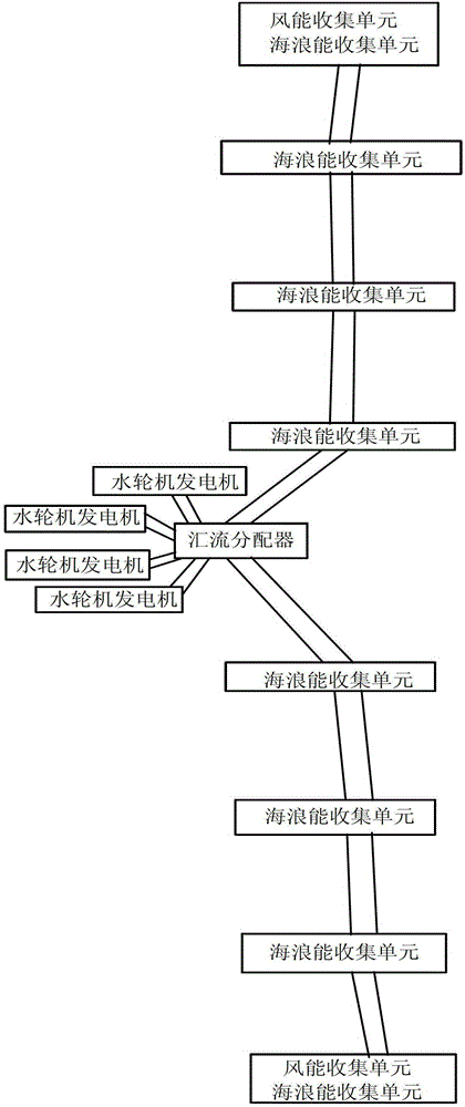
[0038] The energy collection unit of the present invention is a wave energy collection unit and a wind energy collection unit. Others are with embodiment 1 and embodiment 2. At this time, the structure in which the wave energy collection unit and the wind energy collection unit are connected to the same confluence distributor 5 can be adopted, or the structure in which both the wave energy collection unit and the wind energy collection unit are connected to a confluence distributor 5 can also be adopted.
[0039] In the present invention, a brake system should also be provided outside the horizontal turntable 15 to meet the needs of emergency parking or maintenance, and can also be used for speed control in extremely strong winds.
[0040] The theoretical basis of the operating principle of the system of the present invention is: the power of the unstable power source is unstable, and its essence is the irregular change of the power of work. When the working pressure of the hi...
PUM
 Abstract
Description
Claims
Application Information
 - R&D Engineer
- R&D Manager
- IP Professional
- Industry Leading Data Capabilities
- Powerful AI technology
- Patent DNA Extraction
Browse by: Latest US Patents, China's latest patents, Technical Efficacy Thesaurus, Application Domain, Technology Topic, Popular Technical Reports.
© 2024 PatSnap. All rights reserved.Legal|Privacy policy|Modern Slavery Act Transparency Statement|Sitemap|About US| Contact US: help@patsnap.com


