Eureka AIR delivers breakthrough ideas for toughest innovation challenges, trusted by R&D personnel around the world.

Ultrasonic cleaning device and ultrasonic cleaning method

A cleaning device and ultrasonic technology, applied in chemical instruments and methods, cleaning methods and utensils, cleaning methods using liquids, etc., can solve the problems of cleaning objects damage, large ultrasonic vibration amplitude, etc., to prevent re-attachment, inhibit damage, Simplify the effect of ultrasonic cleaning device

Active Publication Date: 2013-07-31
KAIJOO KK
View PDF7 Cites 15 Cited by
  • Summary
  • Abstract
  • Description
  • Claims
  • Application Information

AI Technical Summary

Problems solved by technology

However, when the amplitude of ultrasonic vibration becomes larger, the air bubbles disappear in a positive cycle, and the shock wave generated at this time will cause damage to the object to be cleaned
Especially in the low-frequency ultrasonic wave below 100kHz, the amplitude of ultrasonic vibration is relatively large, which is easy to cause damage to the object to be cleaned

Method used


Image

  • Ultrasonic cleaning device and ultrasonic cleaning method
  • Ultrasonic cleaning device and ultrasonic cleaning method
  • Ultrasonic cleaning device and ultrasonic cleaning method

Examples


no. 1 Embodiment approach ]

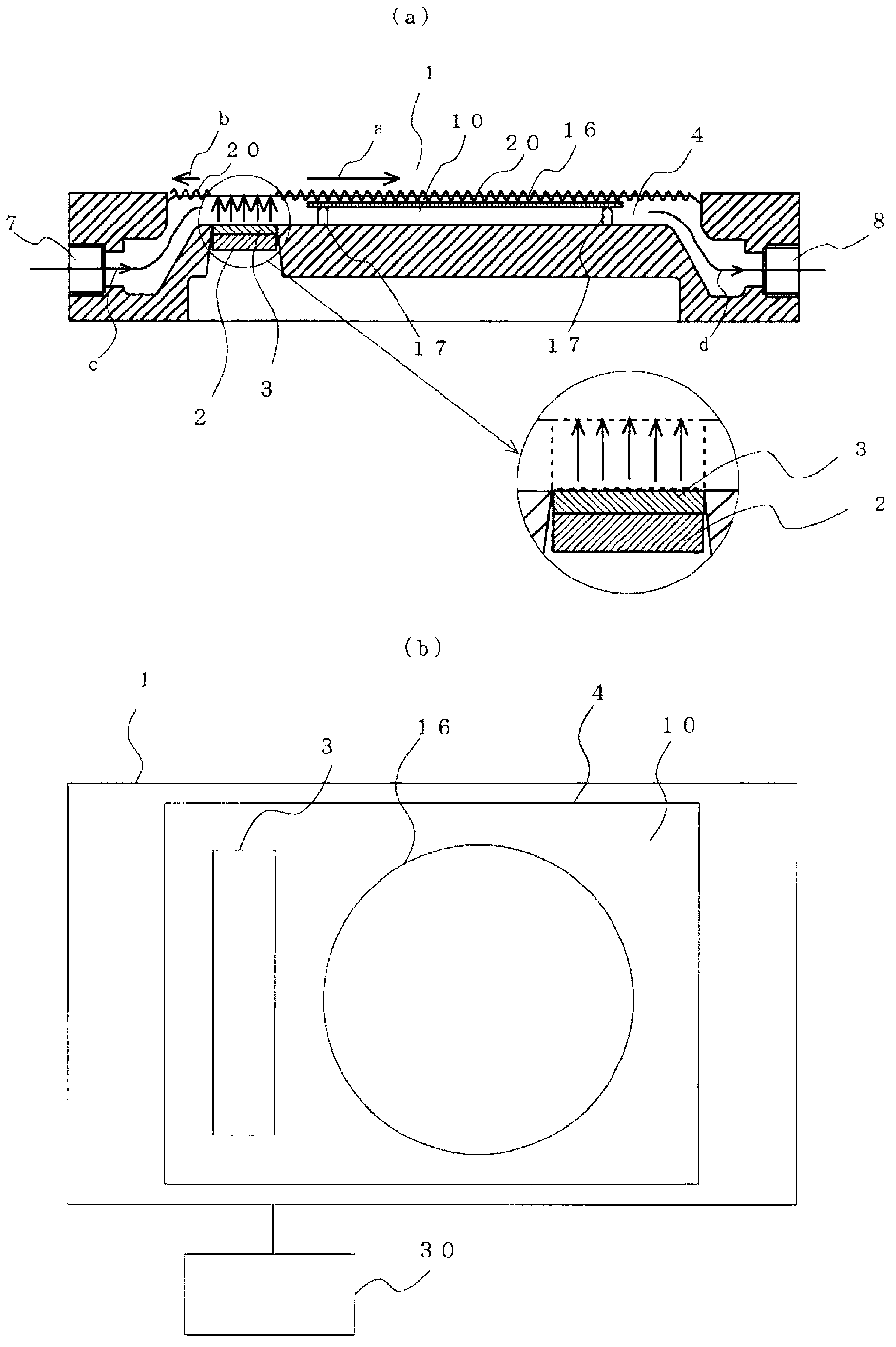
[0060] figure 1 It is a figure which shows the structure of the ultrasonic cleaning apparatus of 1st Embodiment of this invention, figure 1 (a) is a cross-sectional view including a partial enlarged view viewed from the front of the ultrasonic cleaning device, figure 1 (b) is a plan view showing the configuration of the ultrasonic cleaning device. in addition, figure 1 The shown ultrasonic cleaning device is a sheet-type device for processing silicon wafers one by one. Such as figure 1 As shown in (a) and (b), the ultrasonic cleaning device 1 has: a cleaning tank 4 for storing the cleaning solution 10; a cleaning solution supply port 7 ( figure 1 Shown in (a)); the cleaning liquid discharge port 8 provided on the side opposite to the side having the cleaning liquid supply port 7 of the cleaning tank 4 ( figure 1 shown in (a)); the vibrating plate 3 set on the bottom of the cleaning tank 4 near the cleaning liquid supply port 7; the ultrasonic vibrator 2 set on the ...

no. 2 Embodiment approach ]

[0102] Next, an ultrasonic cleaning device according to a second embodiment that cleans an object while moving it will be described. Figure 15 It is a cross-sectional view showing the configuration of an ultrasonic cleaning device according to a second embodiment of the present invention. figure 1 with image 3 The shown ultrasonic cleaning device 1 is cleaned by immersing the object 16 to be cleaned in the cleaning tank 4 and fixing the object 16 to be cleaned, but Figure 15 The illustrated ultrasonic cleaning device 33 cleans while moving the object 16 to be cleaned. Additionally, for figure 1 The same reference numerals are used for the same components, and detailed descriptions of the configurations are omitted.

[0103] Such as Figure 15 As shown, the ultrasonic cleaning device 33 has: a cleaning tank 36 for storing cleaning liquid 10; A supply port 37; a nozzle 35 for spraying high-temperature nitrogen gas. Such as Figure 15 As shown, the bottom of the clean...


PUM


Abstract

Provided is an ultrasonic cleaning device and ultrasonic cleaning method that can suppress occurrences of damage to substrates being cleaned and, additionally, can carry out cleaning with a high degree of cleanliness for substrates and the like, which have high degrees of precision and are used by the electronics industry and the like. An article (16) being cleaned is held so as to be positioned in the proximity of below the surface of a cleaning fluid outside of a region (ultrasonic exposure region) formed by perpendicular lines extending from an oscillation surface of an ultrasonic transducer (2) to the fluid surface. Capillary waves (20) are formed on the surface of the cleaning fluid by ultrasonic waves, and without directly exposing the article being cleaned (16) to the ultrasonic waves, microparticle contamination on the article being cleaned (16) is detached by the sound pressure made by the capillary waves (20), thus suppressing occurrences of damage to the substrate being cleaned.

Description

technical field [0001] The present invention relates to an ultrasonic cleaning device and an ultrasonic cleaning method, and in particular to an ultrasonic cleaning device and an ultrasonic cleaning method capable of performing high-cleanliness cleaning without damaging an object to be cleaned. Background technique [0002] In the electronics industry, the cleaning of glass substrates and silicon wafer substrates requires a high degree of cleanliness. As a method of cleaning such objects to be cleaned, such as substrates, there are a dip method in which a plurality of substrates are immersed in a cleaning solution, and a single sheet method in which a cleaning solution is sprayed on the substrates and the substrates are cleaned one by one. In recent years, the single-sheet system, which can obtain cleaning with a high degree of cleanliness and is also advantageous in terms of cost, is often used. Both the immersion method and the sheet method are cleaning methods in which u...

Claims


Application Information

Patent Timeline
Patent Type & Authority Applications(China)
IPC IPC(8): H01L21/304B08B3/12
CPCH01L21/02052B08B3/12H01L21/67057H01L21/02057H01L21/302
Inventor 铃木一成
Owner KAIJOO KK
Why Eureka
Eureka Blog
Learn More