
Process for producing LED lamp and corresponding LED lamp

A technology of LED lamps and manufacturing methods, applied in the direction of lighting and heating equipment, components of lighting devices, and damage prevention measures for lighting devices, etc., can solve problems such as high consumption, high cost, and adhesives that cannot be dried, and achieve Effective force transmission, chip avoidance and tightening process

Inactive Publication Date: 2013-07-31
OSRAM GMBH
View PDF5 Cites 0 Cited by
  • Summary
  • Abstract
  • Description
  • Claims
  • Application Information

AI Technical Summary

Problems solved by technology

[0004] In addition, the process of tightening is very costly
Alternatively, a possible adhesive connection would also result in a relatively high consumption of adhesive for applying it and create a time pressure (Zeitdruck), in which case all parts must be assembled together and the adhesive would therefore not be able to dry

Method used


Image

  • Process for producing LED lamp and corresponding LED lamp
  • Process for producing LED lamp and corresponding LED lamp
  • Process for producing LED lamp and corresponding LED lamp

Examples


Embodiment Construction

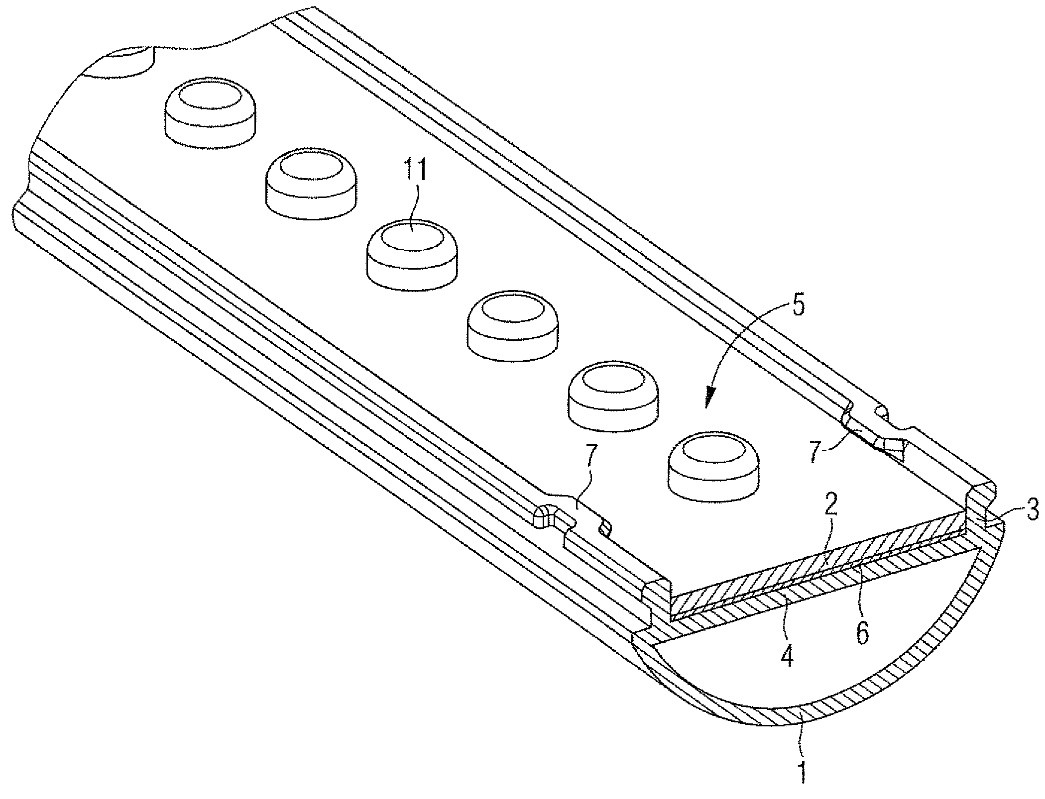
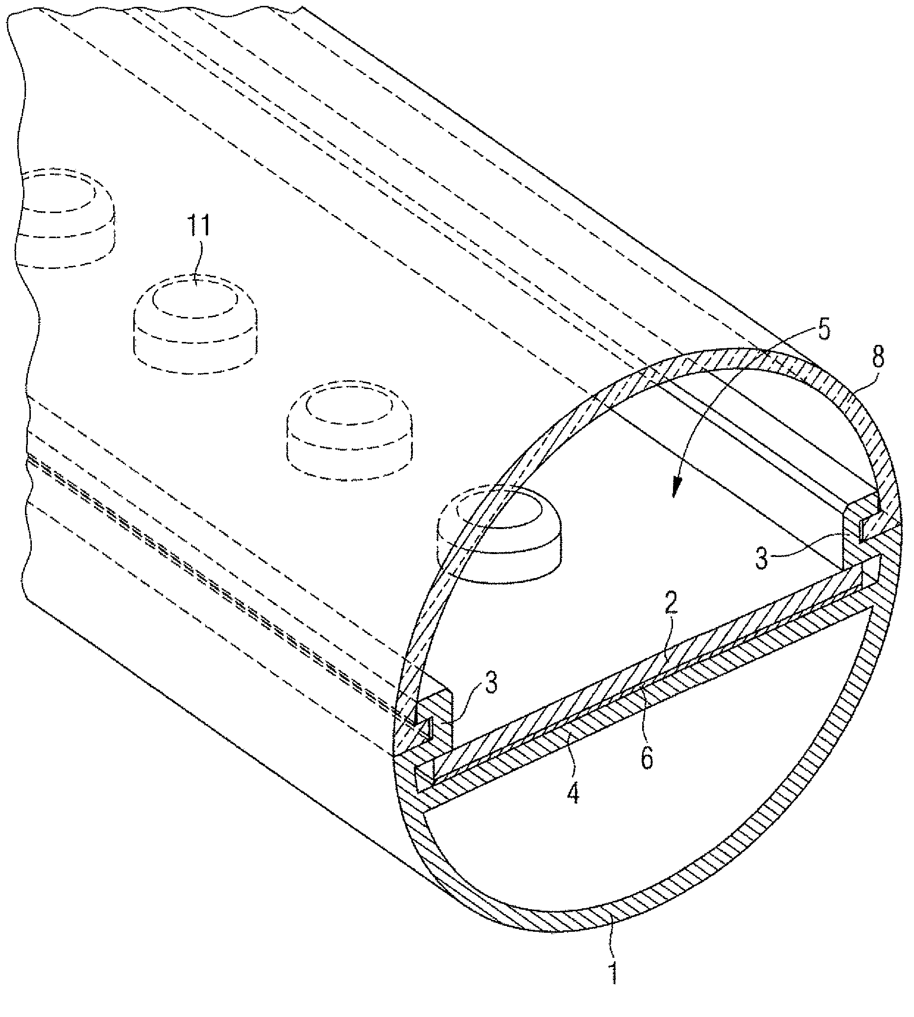
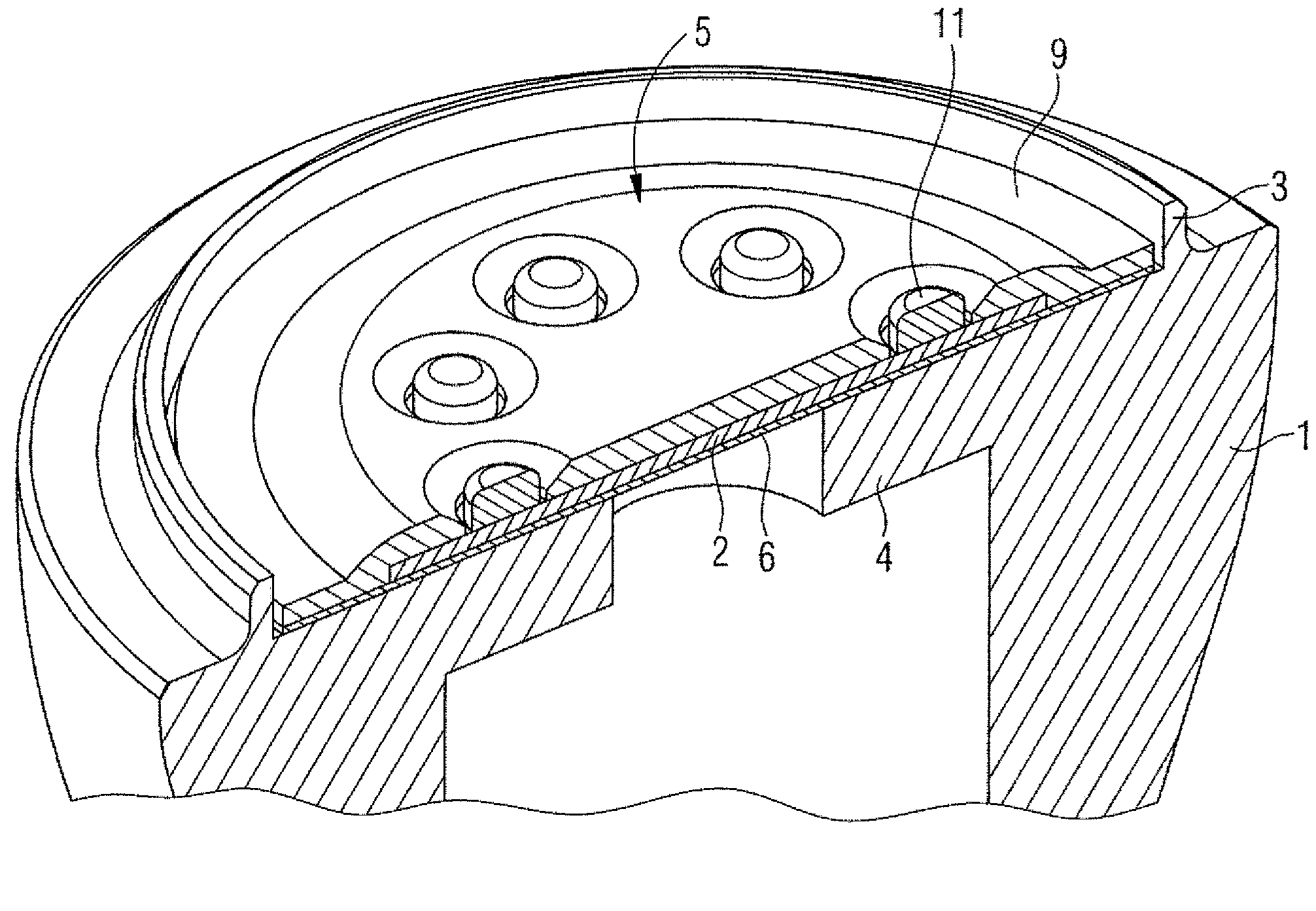
[0026] figure 1 The manufacturing method according to the invention or a first embodiment of an LED lamp (retrofit lamp tube) manufactured according to the invention is shown in a perspective view. exist figure 1 The LED lamp shown in has an approximately semi-cylindrical lamp housing 1 with a central web 4 . All other shapes of lamp housing 1 and carrier circuit board 2 are also conceivable, since they mostly depend on the specific purpose of use. Protruding parts 3 are respectively designed on the left side and the right side of the lamp housing 1 . The carrier circuit board 2 in the lamp housing 1 is arranged between the projections 3 , an insulating layer 6 being introduced between the carrier circuit board 2 and the lamp housing 1 or the central web 4 . In this case, the projection 3 and the central web 4 form a so-called carrier circuit board base 5 , in which the carrier circuit board 2 is arranged. In this case, the carrier circuit board base 5 can be designed in a...


PUM


Abstract

A method for producing an LED lamp includes a lamp housing wherein at least one carrier circuit board equipped with LEDs is inserted into the lamp housing in such a way that at least a subregion of the lamp housing protrudes beyond the carrier circuit board with a projection, and the projection is at least partially deformed after insertion in such a way that the lamp housing is pressed with the carrier circuit board.

Description

technical field [0001] The invention relates to an LED lamp having at least one lamp housing and a carrier circuit board equipped with LEDs. Background technique [0002] In the case of LED retrofit lamps or LED luminaires, the carrier circuit board equipped with LEDs is partially screwed to the lamp housing. This mounting essentially ensures a good heat transfer from the LED via the carrier circuit board to the housing or heat sink. In the case of LED lamps as an alternative to conventional fluorescent lamps, the carrier circuit board equipped with the LEDs is usually also screwed to the lamp housing. [0003] The disadvantage of screw connections is that the lamp housing, which is made of plastic, can break if the screws are over-tightened. In addition, the holes necessary for the screwing create the problem of running the wires through the interior of the cooling body. These conductors carry dangerous grid potentials (Netz-Potential). The insulation of these conductor...

Claims


Application Information

Patent Timeline
Patent Type & Authority Applications(China)
IPC IPC(8): F21V29/00F21Y101/02
CPCF21V15/011F21S4/003F21V19/0035F21V17/005F21V17/08F21V19/005F21V19/004F21Y2103/003F21Y2101/02F21Y2103/022F21V29/22F21V29/70F21S4/20F21Y2115/10F21V29/507F21Y2103/10F21Y2103/33Y10T29/49124
Inventor 哈拉尔德·德利安斯特凡·奥特泽恩法比安·雷因格鲁贝尔托马斯·施马赫特
Owner OSRAM GMBH
Learn More