Combined cycle power plant with CO2 capture and method to operate it

A technology of power equipment and combined cycle, applied in the direction of mechanical equipment, combined combustion mitigation, machine/engine, etc., can solve the problems of absorption solution deterioration, CO2 capture equipment efficiency increase, CO2 capture equipment operation and maintenance cost increase, etc. Achieve increased flexibility, improved performance and profitability, and increased efficiency

Inactive Publication Date: 2013-07-31
ALSTOM TECH LTD
View PDF5 Cites 3 Cited by
  • Summary
  • Abstract
  • Description
  • Claims
  • Application Information

AI Technical Summary

Problems solved by technology

For example, recirculation of exhaust gas back to the gas turbine compressor inlet can result in a doubling of the concentration of the exhaust gas to the CO2 capture plant and a consequent increase in the efficiency of the CO2 capture plant
[0005] It is also known that the concentration of oxygen in the exhaust gas affects the operation of CO2 capture plants, as oxygen can cause degradation of the absorption solution, which can lead to increased operating and maintenance costs of CO2 capture plants

Method used


Image

  • Combined cycle power plant with CO2 capture and method to operate it
  • Combined cycle power plant with CO2 capture and method to operate it
  • Combined cycle power plant with CO2 capture and method to operate it

Examples


Embodiment Construction

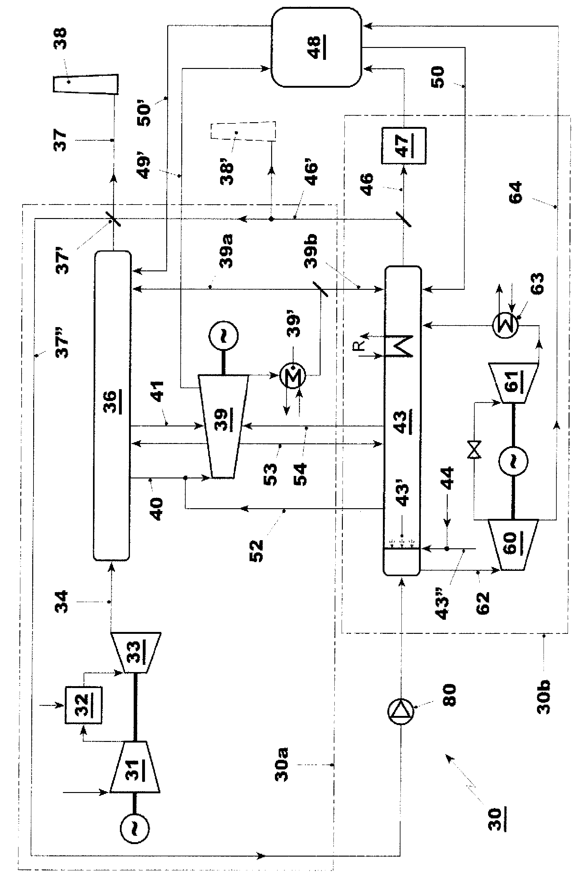
[0048] The power plant 30 for generating electric power according to the present invention as shown in FIGS. A combined cycle power plant with a gas turbine 33 driving an electric generator. Exhaust lines 34 , 35 lead exhaust gas from the gas turbine to a first HRSG 36 where it is used for steam generation and then through an exhaust gas line 37 which leads the exhaust gas to a stack 38 .

[0049] The steam generated in the first HRSG is passed via live steam line 40 to a steam turbine 39 which in turn drives another generator. The steam discharged by the steam turbine 39 is passed into the condenser 39', and the resulting condensate is introduced into the HRSG 36 via line 39a for steam generation, thereby completing the water steam cycle.

[0050] The unit 30b of the power plant 30 mainly comprises a second HRSG 43 operating with the hot exhaust gas from the unit 30a branched from the exhaust line 34 by means of a baffle or flow divider 34'. The exhaust is used for hea...


PUM


Abstract

A combined cycle power plant with a gas turbine, steam turbine, and first HRSG comprises a CO2 capture plant for the at least partial capture of CO2 from the exhaust gases from the gas turbine. It comprises in particular a second HRSG or boiler arranged to receive a portion of the exhaust gases and transfer its heat to steam and feedwater. Steam generated in the second HRSG or boiler is used for the operation of the CO2 capture plant and / or to operate a steam turbine that drives a generator and optionally a CO2 compressor. The power plant according to the invention allows for greater flexibility in power plant part load control and power plant efficiency. A method to operate the power plant is also claimed.

Description

technical field [0001] The present invention relates to a combined cycle power plant for generating electrical energy comprising a gas turbine, a steam turbine, a heat recovery steam generator, and integrated in the power plant for capturing and compressing the gas turbine exhaust Carbon dioxide equipment. The invention also relates to a method of operating the power plant. Background technique [0002] Combined cycle power plants with carbon dioxide (CO2) capture are well known in the literature and have been implemented in first test power plants, eg in the US and Sweden. [0003] Known concepts for such power plants with carbon dioxide capture devices include combined cycle power plants with gas and steam turbines and heat recovery steam generators (HRSG) designed to generate steam using heat from the gas turbine exhaust. Exhaust gases from such HRSGs usually contain only up to about 4% of the volume flow of CO 2 . CO2 capture plants have been proposed that capture CO2...

Claims


Application Information

Patent Timeline
Patent Type & Authority Applications(China)
IPC IPC(8): F02C6/18F01K23/10
CPCY02E20/16Y02C10/04F01K23/10F02C6/18F01K17/04Y02E20/32
Inventor 李洪涛F.德鲁克斯C.鲁希蒂K.雷泽
Owner ALSTOM TECH LTD
Why Eureka
Try Eureka