Detection apparatus and method for receiving signal intensity indication
A technology of received signal strength and detection device, applied in the microwave field, can solve the problems of amplification control signal hopping, analog-digital conversion unit receiving data stream power hopping, bit error and other problems
- Summary
- Abstract
- Description
- Claims
- Application Information
AI Technical Summary
Problems solved by technology
Method used
Image
Examples
Embodiment 1
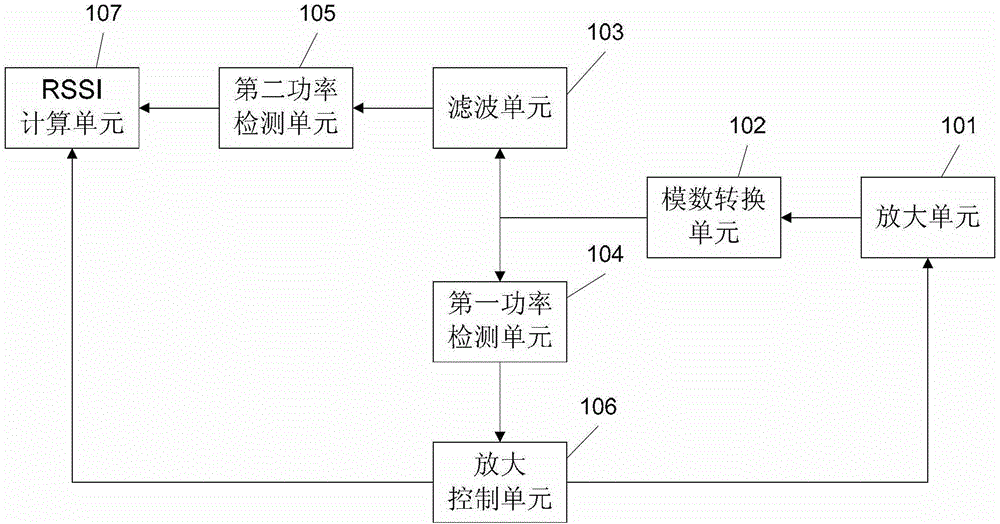
[0024] figure 1 The structure of an RSSI detection device provided by the first embodiment of the present invention is shown. The detection device is located in the microwave receiving end. The detection device in this embodiment includes:
[0025] The amplifying unit 101 is configured to receive the modulated signal data stream from the microwave transmitting end, and amplify the modulated signal data stream according to the amplification control signal, and the amplification control signal is used to instruct the amplifying unit to perform the modulated signal data stream Send the amplified modulated signal data stream to the analog-to-digital conversion unit 102;
[0026] In this embodiment, the amplifying unit may be a VGA (Voltage Gain Amplifier, voltage controlled gain amplifier). VGA is a device that controls the gain of a voltage device. It has two inputs, one of which is a signal input, that is, the signal input from the microwave transmitting end. The modulated signal dat...
Embodiment 2
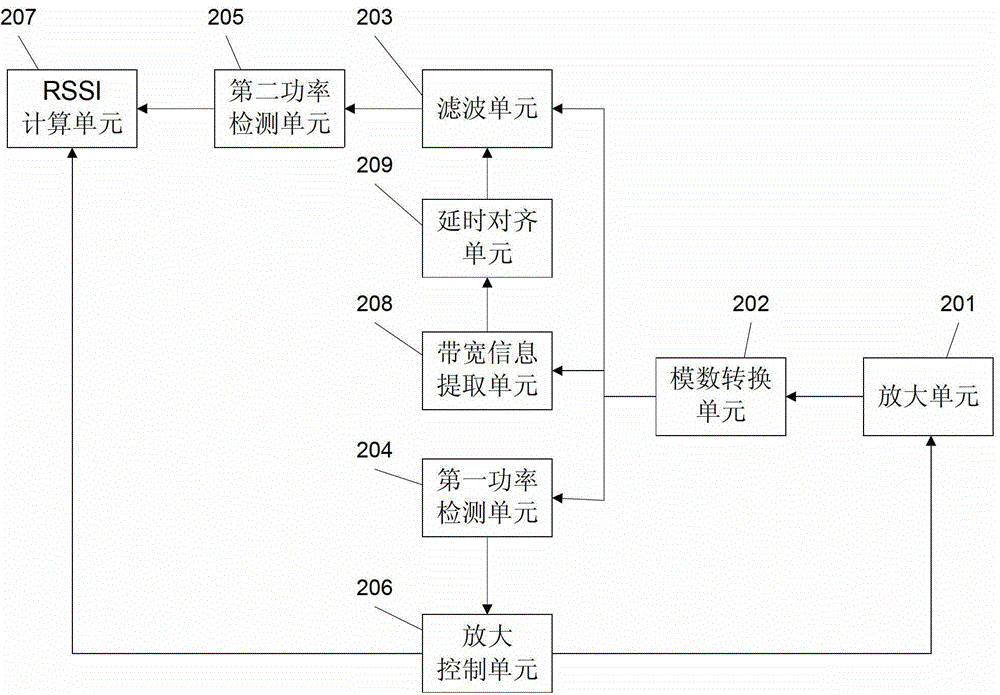
[0046] figure 2 The structure of an RSSI detection device provided by the second embodiment of the present invention is shown. The detection device is located in the microwave receiving end. The detection device in this embodiment includes:
[0047] The amplifying unit 201 is configured to receive the modulated signal data stream from the microwave transmitting end, and amplify the modulated signal data stream according to the amplification control signal, and the amplification control signal is used to instruct the amplifying unit to perform the modulated signal data stream. Send the amplified modulated signal data stream to the analog-to-digital conversion unit 202;
[0048] In this embodiment, the amplifying unit may be a VGA. The VGA is a voltage control device gain device with two inputs. One input is the signal input, that is, the modulated signal data stream from the microwave transmitting end, and the other is the control voltage. Input, the modulated signal data stream en...
Embodiment 3
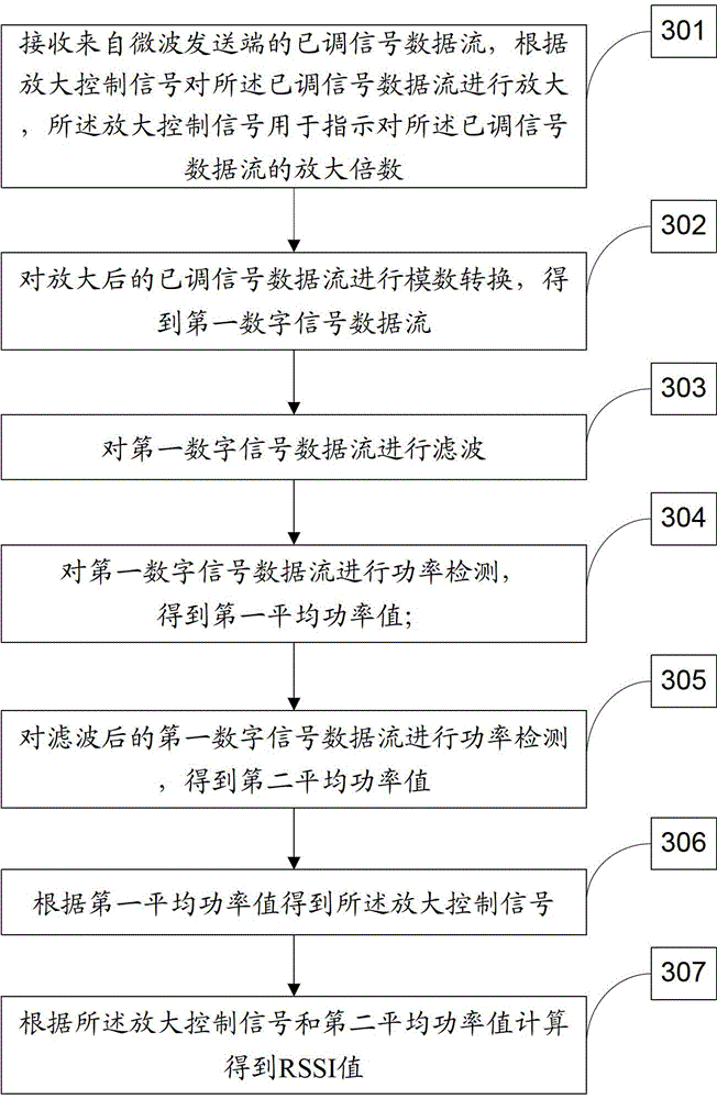
[0076] image 3 The flow of an RSSI detection method provided by the third embodiment of the present invention is shown. The method in this embodiment includes the following steps:
[0077] S301: Receive a modulated signal data stream from a microwave transmitting end, and amplify the modulated signal data stream according to an amplification control signal, where the amplification control signal is used to indicate an amplification factor for the modulated signal data stream;
[0078] S302: Perform analog-to-digital conversion on the amplified modulated signal data stream to obtain a first digital signal data stream;
[0079] S303: Filter the first digital signal data stream.
[0080] In this embodiment, bandwidth-matched filtering is performed on the first digital signal data stream, and the bandwidth of the first digital signal data stream is the same as the bandwidth of the filter channel.
[0081] In order to achieve bandwidth-matched filtering, the bandwidth of the filter channel ...
PUM
 Abstract
Description
Claims
Application Information
 - R&D
- Intellectual Property
- Life Sciences
- Materials
- Tech Scout
- Unparalleled Data Quality
- Higher Quality Content
- 60% Fewer Hallucinations
Browse by: Latest US Patents, China's latest patents, Technical Efficacy Thesaurus, Application Domain, Technology Topic, Popular Technical Reports.
© 2025 PatSnap. All rights reserved.Legal|Privacy policy|Modern Slavery Act Transparency Statement|Sitemap|About US| Contact US: help@patsnap.com


