
Method, terminal and base station for uplink interference cancellation

An interference cancellation and terminal technology, applied in the direction of error prevention/detection, location diversity, power management, etc. using the return channel, which can solve problems such as the performance impact of uplink JR technology, and achieve the effect of improving performance

Inactive Publication Date: 2013-07-24
ZTE CORP
View PDF3 Cites 13 Cited by
  • Summary
  • Abstract
  • Description
  • Claims
  • Application Information

AI Technical Summary

Problems solved by technology

[0010] According to the technical characteristics of uplink and downlink CoMP, it can be seen that the downlink CoMP technology can not only realize the coordination of precoding, but also reduce the interference, while the uplink CoMP technology only increases the received energy and has no effect on interference suppression. Interference suppression technology is used in combination with CoMP technology. For example, JR reception based on the Linear Minimum Mean Square Error (LMMSE, Linear Minimum Mean Square Error) criterion is also a passive interference suppression technology, and it cannot transmit When considering interference cancellation, that is, pre-elimination of interference at the sending end; thus, the performance of the uplink JR technology will be affected

Method used


Image

  • Method, terminal and base station for uplink interference cancellation
  • Method, terminal and base station for uplink interference cancellation
  • Method, terminal and base station for uplink interference cancellation

Examples


Embodiment Construction

[0076] The technical solutions of the present invention will be further elaborated below in conjunction with the accompanying drawings and specific embodiments.

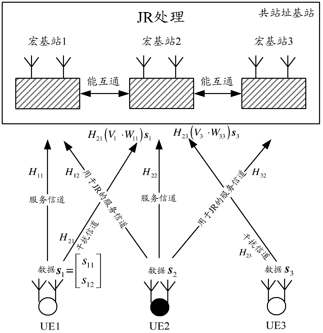
[0077] A method for canceling uplink interference provided by an embodiment of the present invention is as follows: figure 1 As shown, it mainly includes:

[0078] Step 101, the terminal receives precoding information from the serving base station, and adjusts the precoding information according to the obtained channel state information between the terminal and the coordinated base station to obtain an adjusted precoding matrix.

[0079] The terminal in the embodiment of the present invention is designated by the serving base station.

[0080] In frequency division duplex (FDD, Frequency Division Duplexing) mode, the channel state information between the terminal and the coordinated base station is measured by the coordinated base station; the coordinated base station notifies the serving base station of the measure...


PUM


Abstract

The invention discloses a method, a terminal and a base station for uplink interference cancellation. The terminal receives precoding information from a service base station, the precoding information is adjusted according to channel state information from the terminal to a collaborative base station, and data are sent to the service base station according to an obtained adjusted precoding matrix. The service base station or the collaborative base station adjusts the precoding information used by the terminal according to the channel state information from the terminal to the collaborative base station to obtain adjusted precoding matrix information, the service base station or the collaborative base station sends the adjusted precoding matrix information to the terminal, and the terminal sends data to the service base station according to the adjusted precoding matrix. The service base station or the collaborative base station adjusts the precoding information used by the terminal according to the channel state information from the terminal to the collaborative base station to obtain the adjusted matrix information, the service base station or the collaborative base station sends an adjusted matrix and the precoding information used by the terminal to the terminal, and the terminal adjusts the used precoding information to obtain an adjusted precoding matrix according to the adjusted matrix and sends data to the service base station according to the adjusted precoding matrix. The method, the terminal and the base station for the uplink interference cancellation can achieve interference suppression at a sending end.

Description

technical field [0001] The present invention relates to the technical field of wireless communication, in particular to a method for canceling uplink interference, a terminal and a base station. Background technique [0002] With the rapid development of wireless communication technology, insufficient spectrum resources have gradually become the main factor restricting the development of wireless communication; how to make full use of limited spectrum resources and improve spectrum utilization is a major problem in wireless communication. Multiple-Input Multiple-Output (MIMO, Multiple-Input Multiple-Output) technology is widely favored because it can improve transmission efficiency and spectrum utilization without increasing bandwidth. MIMO technology utilizes space diversity gain through transmit and receive diversity, antenna array gain through beamforming technology, and spatial multiplexing gain through spatial multiplexing technology. Specifically, the acquisition dive...

Claims


Application Information

Patent Timeline
Patent Type & Authority Applications(China)
IPC IPC(8): H04L1/06H04L1/18H04W52/42
CPCH04B7/0404H04B7/024H04J11/003H04B7/0413
Inventor 关艳峰罗薇张峻峰
Owner ZTE CORP
Learn More