
Gain control index testing method of radio frequency receiver

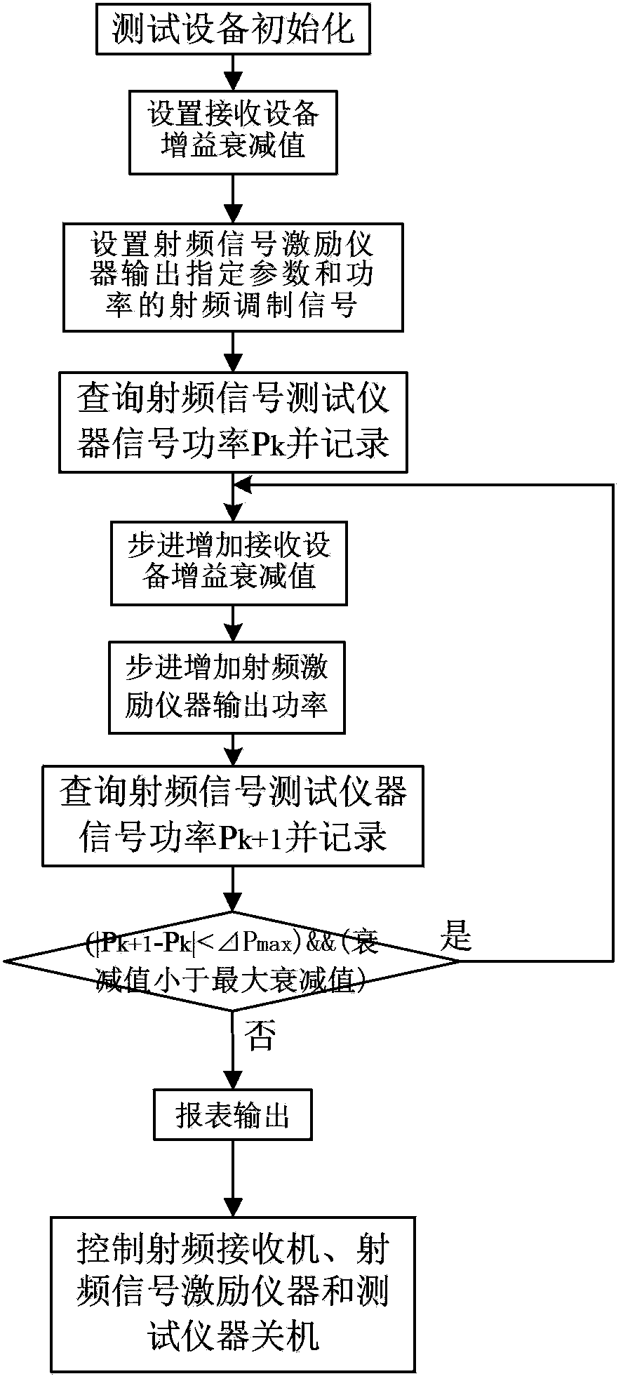
A radio frequency receiver and gain control technology, which is applied in receiver monitoring and other directions, can solve the problems of cumbersome receiver gain control index testing, large influence of human factors, and low degree of automation, so as to improve information utilization efficiency and reduce manpower input , to achieve the effect of automation

Inactive Publication Date: 2015-02-18
NORTHWESTERN POLYTECHNICAL UNIV
View PDF3 Cites 0 Cited by
  • Summary
  • Abstract
  • Description
  • Claims
  • Application Information

AI Technical Summary

Problems solved by technology

[0005] The invention proposes an automatic test method for the gain control index of the radio frequency receiver to solve the problems that the existing receiver gain control index test work is cumbersome, the degree of automation is low, and the human factors are greatly affected, replacing the manual operation of the test receiver. The backward method of gain control effectively avoids the cumulative error of manual testing and reduces manpower input

Method used


Image

  • Gain control index testing method of radio frequency receiver
  • Gain control index testing method of radio frequency receiver

Examples


Embodiment Construction

[0018] The invention discloses a method for testing the gain control index of a radio frequency receiver. The invention can effectively improve the automation degree of the gain control index test and reduce the influence of human factors on the index. The test connection is as follows: figure 1 shown.

[0019] The present invention will be further described below in conjunction with the accompanying drawings and embodiments.

[0020] Step 1: Set the RF signal on the main control computer to stimulate the instrument to output continuous pulse waves. The output frequency is based on the main receiving frequency f of the RF receiving device under test, and the output power is |P 损 |+P normal , the unit is dB, P 损 In order to test the RF signal power loss of the cable channel, the connection loss obtained by measuring the RF signal input and output at both ends of the cable, P 损 =P i -P o , P i is the RF signal power input at the cable input end, P o is the RF signal power...


PUM


Abstract

The invention provides a gain control index testing method of a radio frequency receiver. The gain control index testing method of the radio frequency receiver includes the following steps: sending an instruction from a main control computer to a radio frequency signal tester to inquire radio frequency signal power, recording a power peak value as Pk, recording a power peak value obtained after power is increased step by step as Pk+1, judging whether an absolute error between the PK+1 and the Pk is larger than delta Pmax or not, if the absolute error is smaller than the delta Pmax and a gain attenuation value of a presently tested radio frequency receiving device is smaller than a maximum attenuation value of the tested radio frequency receiving device, repeating the inquiring process, and if the absolute error between the PK+1 and the Pk is larger than the delta Pmax or the gain attenuation value of the presently tested radio frequency receiving device is larger than or equal to the maximum attenuation value of the tested radio frequency receiving device, ending the test. The gain control index testing method of the radio frequency receiver is controlled by a computer, compared with a manual testing method, the gain control index testing method of the radio frequency receiver improves information utilization rate and is automatic in testing process. Testing results are accurately and rapidly output, accumulative errors are avoided, and data recording is complete, detailed and accurate.

Description

technical field [0001] The invention relates to a test method for receiving signal gain control of a radio frequency receiver, in particular to a test method for a receiver signal receiving gain control index based on a virtual instrument. Background technique [0002] The gain control index refers to the ability to receive and gain control the signal, and is a key indicator of the ability to adjust the strength of the RF receiver signal reception, and its performance status directly affects the performance of the entire RF receiving device. As the signal receiving and initial processing equipment of the radio frequency receiving equipment, the receiving front end will have problems such as aging of components with the increase of working time, and its signal receiving adjustment ability will be weakened, which will affect the reception of weak signals. [0003] The gain control index of the input signal can effectively reflect the working performance of the receiver, preven...

Claims


Application Information

Patent Timeline
Patent Type & Authority Patents(China)
IPC IPC(8): H04B17/29
Inventor 陈杰马存宝宋东和麟张天伟
Owner NORTHWESTERN POLYTECHNICAL UNIV
Learn More