
plasma vortex generator

A vortex generator and plasma technology, applied in the direction of generating vortices, reducing drag, etc., can solve problems such as work efficiency decline and failure, and achieve the effects of simple device, low power consumption, and improved flow field structure.

Active Publication Date: 2015-10-07
BEIHANG UNIV
View PDF6 Cites 0 Cited by
  • Summary
  • Abstract
  • Description
  • Claims
  • Application Information

AI Technical Summary

Problems solved by technology

However, the biggest defect of the jet vortex generator is that it needs an air source with sufficient power to generate the jet, and secondly, the blockage of the jet orifice by dust and foreign matter particles will cause a decrease in work efficiency or even failure.

Method used


Image

  • plasma vortex generator
  • plasma vortex generator
  • plasma vortex generator

Examples


Embodiment Construction

[0034] The present invention will be further described in detail with reference to the accompanying drawings and embodiments.

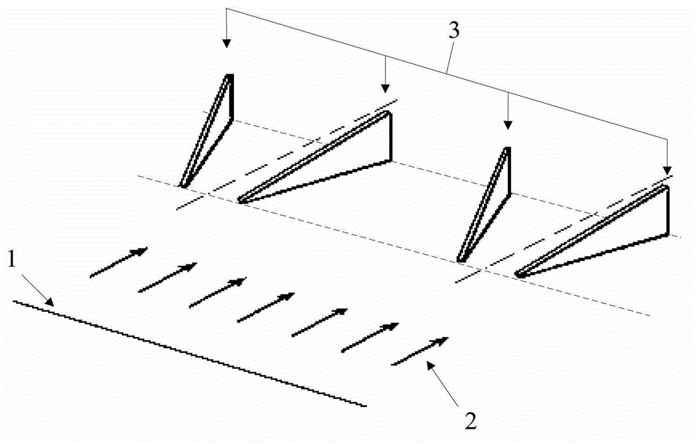
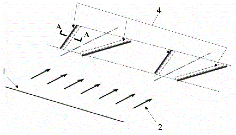
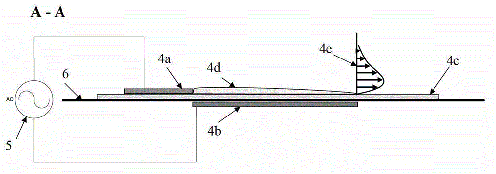
[0035] The present invention proposes a plasma vortex generator, which is realized through a specific layout of a plasma actuator on a control body such as a flat plate or an airfoil. One or more groups of plasma exciters are attached near the front edge of the separation area near the surface of the control body such as the wing or flat plate. The wall jet has a certain deflection angle with the direction of the free flow, so that the interaction produces a flow direction vortex, which strengthens the momentum in the boundary layer and achieves the purpose of inhibiting or delaying the flow separation. The wind tunnel flow display experiment shows that the vortex generator based on the asymmetric dielectric barrier discharge plasma exciter proposed by the present invention can generate a flow direction vortex, and this flow direction vortex has a str...


PUM


Abstract

The invention provides a plasma vortex generator, which is realized through more than one plasma exciter attached at the front edge of a separation region on the surface of a control body along the spreading direction; an angle of 0-45 degrees exists between the longitudinal direction of each plasma exciter and a free incoming flow; an upper layer of bare electrode of each plasma exciter is in the upper stream corresponding to a lower layer of covered electrode; the covered electrode and the bare electrode are not overlapped in the width direction of each plasma exciter; each plasma exciters generate a wall surface jet flow pointing to the corresponding covered electrode from the corresponding bare electrode; and each wall surface jet flow and a natural incoming flow are interacted to generate a vortex along the direction of the free incoming flow. Compared with the traditional vortex generator, additional resistance can not be caused; furthermore, the plasma vortex generator disclosed by the invention is simple in structure, easy for installation and realization and free from extra air sources; and simultaneously, real-time active control and non-stationary control of wing rising can be realized.

Description

technical field [0001] The present invention relates to a vortex generator, in particular to a novel plasma vortex generator, in which one or more plasma actuators induce jet flow to interact with the main flow to form a vortex along the flow direction, which enhances the connection between the inside of the boundary layer and the incoming flow. Momentum exchange between them, thereby inhibiting or delaying flow separation. Background technique [0002] In the field of aerospace engineering, flow separation control technology has always been the focus of researchers. As a commonly used control flow separation method, the vortex generator can exchange or balance the high-momentum airflow in the main flow outside the boundary layer with the low-momentum airflow in the near-wall area by generating vortices, thereby increasing the airflow inside the boundary layer and preventing Boundary layer separation formed by an adverse pressure gradient. [0003] Early vortex generators ...

Claims


Application Information

Patent Timeline
Patent Type & Authority Patents(China)
IPC IPC(8): B64C23/06
CPCY02T50/162Y02T50/10
Inventor 冯立好王晋军史涛瑜刘亚光
Owner BEIHANG UNIV
Learn More