Turbine self-priming movable multifunctional flood fighting, irrigation and drainage pump truck set
A mobile and multi-functional technology, which is applied in the direction of motor vehicles, vehicle parts, article transport vehicles, etc., can solve the problems of slow start, difficult discharge of dangerous situations, etc., and achieve the effect of fast water discharge and flexible mobility
- Summary
- Abstract
- Description
- Claims
- Application Information
AI Technical Summary
Problems solved by technology
Method used
Image
Examples
Embodiment 1
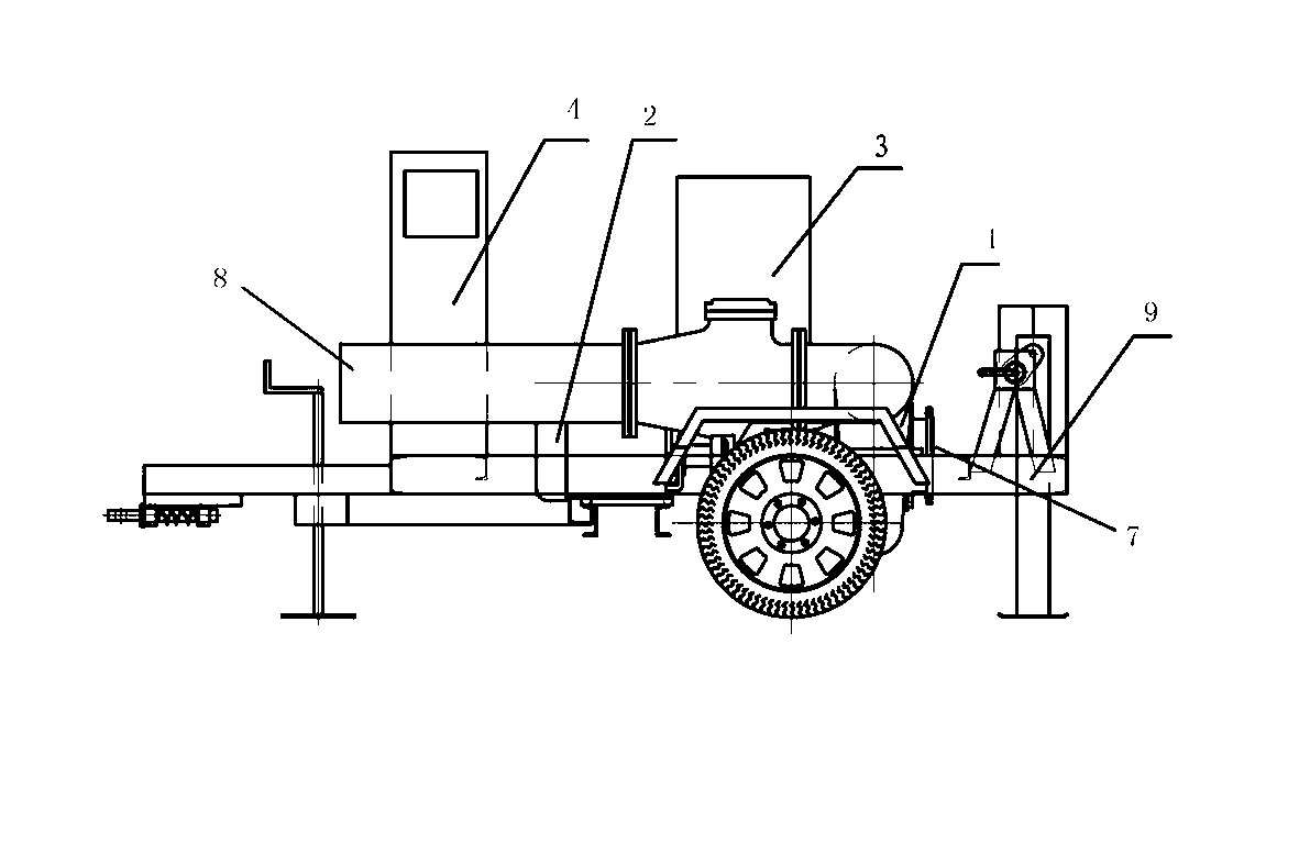
[0020] Such as figure 1 and Figure 5 As shown, a motor or diesel engine-driven pump structure in the form of a trailer is adopted, including a lift drainage pump 1, a turbo vacuum machine 3, a motor 2 or a diesel engine 10 and a control cabinet 4, and the lift drainage pump 1, turbo vacuum machine 3, motor 2 or the diesel engine 10 and the control cabinet 5 are installed together on the trailer 9. The electric motor 2 or the diesel engine 10 transmits power to the lift drainage pump 1 through a coupling. The suction pipe of the turbo vacuum machine 3 is airtightly connected with the pump cavity of the lift drainage pump 1 . The control cabinet 4 controls the entire operation process of the turbo vacuum machine 3 and the lift drainage pump 1 .
Embodiment 2
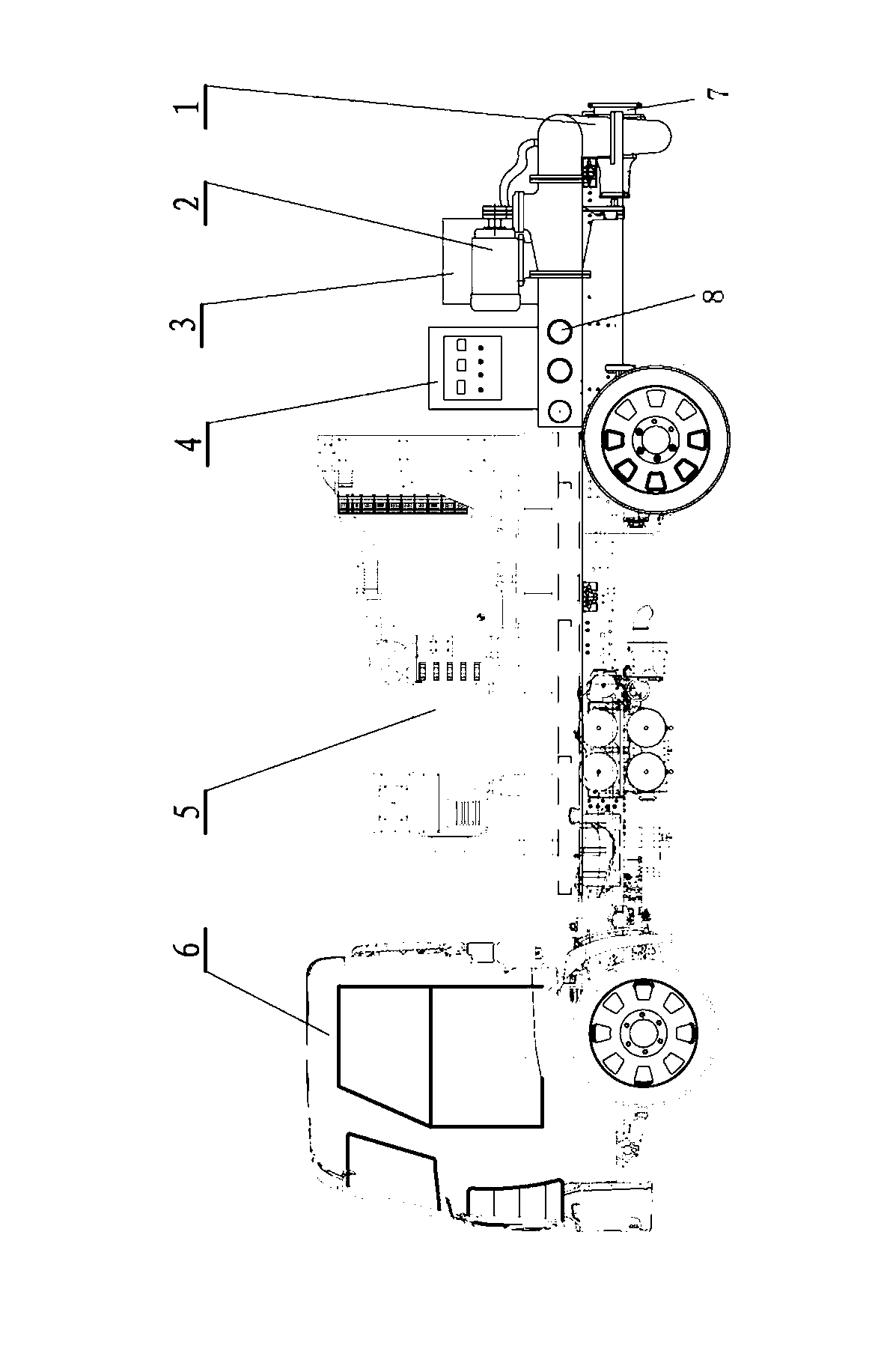
[0022] Such as figure 2 and Figure 4 As shown, the pump structure is driven by a diesel generator in the form of an automobile, including a lift drainage pump 1, a motor 2, a turbo vacuum machine 3, a control cabinet 4, a diesel generator set 5 and a vehicle 6, and the lift drainage pump 1, motor 2 , turbo vacuum machine 3, control cabinet 4 and diesel generator set 5 are installed on the automobile 6 together. The diesel generator set 5 provides power to the turbo vacuum machine 3 and the electric motor 2 . The suction pipe of the turbo vacuum machine 3 is airtightly connected with the pump cavity of the lift drainage pump 1, the motor 2 transmits power to the lift drainage pump 1 through a coupling, and the control cabinet 4 controls Follow the entire operation process of the turbo vacuum machine 3 and the lift drainage pump 1. attached figure 2 The pump is arranged horizontally, with Figure 4 The pump and motor are installed vertically with the shaft end facing upw...
Embodiment 3
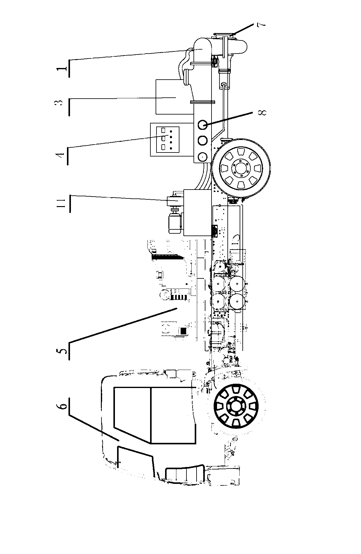
[0024] Such as image 3 As shown, adopt automobile form diesel generator set and hydraulically driven pump structure, including lift drainage pump 1, turbine vacuum machine 3, control cabinet 4, hydraulic pump station 11, diesel generator set 5 and automobile 6, described lift drainage pump 1. The turbo vacuum machine 3, the control cabinet 4, the hydraulic pump station 11 and the diesel generator set 5 are installed on the car 6 together. Described diesel generator set 5 provides power supply to turbo vacuum machine 3 and hydraulic pump station 11. The suction pipe of the turbo vacuum machine 3 is airtightly connected with the pump cavity of the lift drainage pump 1, the hydraulic pump station 11 transmits power to the lift drainage pump 1 through a hydraulic motor, and the control cabinet 4, It controls the entire operation process of the turbo vacuum machine 3 and the lifting drainage pump 1.
[0025] The center line of the pump of the turbine self-irrigating mobile multi...
PUM
 Abstract
Description
Claims
Application Information
 - R&D
- Intellectual Property
- Life Sciences
- Materials
- Tech Scout
- Unparalleled Data Quality
- Higher Quality Content
- 60% Fewer Hallucinations
Browse by: Latest US Patents, China's latest patents, Technical Efficacy Thesaurus, Application Domain, Technology Topic, Popular Technical Reports.
© 2025 PatSnap. All rights reserved.Legal|Privacy policy|Modern Slavery Act Transparency Statement|Sitemap|About US| Contact US: help@patsnap.com


