
Low-common-mode-noise grid-connected inverter circuit and reactive power control method

An inverter circuit and circuit technology, applied in the direction of converting irreversible DC power input to AC power output, control/regulation systems, output power conversion devices, etc., can solve large switching noise and current ripple amplitude, harmonics, etc. Wave distortion, common mode noise interference, large change in common mode voltage amplitude, etc., to achieve the effect of suppressing common mode current, reducing EMI, and strong overload capacity

Inactive Publication Date: 2013-07-17
牟英峰
View PDF6 Cites 12 Cited by
  • Summary
  • Abstract
  • Description
  • Claims
  • Application Information

AI Technical Summary

Problems solved by technology

In the bipolar modulation circuit, the four switching tubes (shown in the dotted line box) all work at a relatively high switching frequency, the loss of the switching tube is large, which affects the efficiency, and there is a large switching noise and current ripple amplitude
In a unipolar modulation circuit, the amplitude of the common-mode voltage generated by the inverter varies greatly, and the resulting common-mode current increases linearly with the increase of the switching frequency, and the harmonic distortion and common-mode noise interference are serious

Method used


Image

  • Low-common-mode-noise grid-connected inverter circuit and reactive power control method
  • Low-common-mode-noise grid-connected inverter circuit and reactive power control method
  • Low-common-mode-noise grid-connected inverter circuit and reactive power control method

Examples


Embodiment Construction

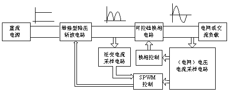
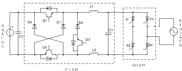
[0034] Such as figure 1 , image 3 , Figure 4 As shown, the DC / AC grid-connected inverter circuit includes enhanced step-down chopper circuit, thyristor commutation circuit, inverter current sampling circuit, voltage and current detection circuit, thyristor commutation control circuit and SPWM control circuit .

[0035] The enhanced step-down chopper circuit includes power switch Q1 (MOSFET or IGBT), power switch Q2 (MOSFET or IGBT), power switch Q3 (MOSFET or IGBT), diode D1, diode D2, diode D3, inductor L1, inductor L2, capacitor C1 and low frequency switch Q3, the drain (or collector) of power switch Q1 is connected to the anode of DC power supply and the cathode of diode D2, and its source (or emitter) is connected to one end of inductor L1, the cathode of diode D1 and the cathode of diode D3 The cathode is connected; the drain (or collector) of the power switch tube Q2 is connected to the anode of the diode D2, one end of the inductor L2 is connected to the source (o...


PUM


Abstract

The invention relates to a low-common-mode-noise grid-connected inverter circuit and a reactive power control method. The low-common-mode-noise grid-connected inverter circuit comprises an enhanced voltage-reducing chopper circuit and a silicon controlled rectifier power frequency phase-changing circuit, wherein the enhanced voltage-reducing chopper circuit comprises a power switch tube modulated through sinusoidal pulse width modulation (SPWM), a double-follow-current diode, a power-factor control power switch tube, an inductor and a capacitor. The direct current electric energy is converted into sine semiwaves by adjusting the duty ratio of high-frequency switch tubes in the enhanced voltage-reducing chopper circuit. The power-factor can be adjusted by adjusting a conducting mode of the power-factor control power switch tube. The phase-changing circuit consisting of four low-frequency silicon controlled rectifiers performs phase changing on the direct current sine semiwave to obtain full sine waves and finishes inversion from the direct current to the sine alternating current. Compared with conventional full-bridge grid-connected inverter circuits, the low-common-mode-noise grid-connected inverter circuit is simple in structure, strong in overcurrent-resisting capacity, high in stability and inversion efficiency and low in cost, and the number of the high-frequency switch tubes is approximately decreased by one half. Due to the fact that a whole inversion loop is fully symmetrical in the switching and phase-changing process, the common-mode voltage produced by inverted alternating-current output is constant, the common-mode current is restrained, and electro-magnetic interference (EMI) is reduced.

Description

technical field [0001] The invention relates to a grid-connected inverter circuit with low common-mode noise and a reactive power control method, especially a DC / AC grid-connected inverter with high conversion efficiency and low harmonic distortion, and capable of power factor adjustment at the same time. Transformer circuit and reactive power regulation method. Background technique [0002] The function of the grid-connected inverter circuit is to convert the DC voltage into a sinusoidal AC, and realize the grid-connected power supply for electrical equipment. High efficiency and low harmonic distortion are the key indicators of this technology; when connecting to the grid for power generation, it is also necessary to adjust the power factor according to the power dispatching instruction. [0003] The existing grid-connected inverter technology mostly adopts a four-tube full-bridge circuit structure, such as figure 2 Shown, using bipolar modulation or unipolar modulation....

Claims


Application Information

Patent Timeline
IPC IPC(8): H02M7/48H02M3/155H02M7/521H02M1/44
Inventor 丁宝孙立峰牟英峰
Owner 牟英峰
Learn More