
Carrier Device And Robot System

A technology of robot system and handling device, applied in the field of handling device and robot system to achieve the effect of reducing operation space

Active Publication Date: 2013-07-17
YASKAWA DENKI KK
View PDF4 Cites 12 Cited by
  • Summary
  • Abstract
  • Description
  • Claims
  • Application Information

AI Technical Summary

Problems solved by technology

This results in extending the cable more than necessary

Method used


Image

  • Carrier Device And Robot System
  • Carrier Device And Robot System
  • Carrier Device And Robot System

Examples


Embodiment Construction

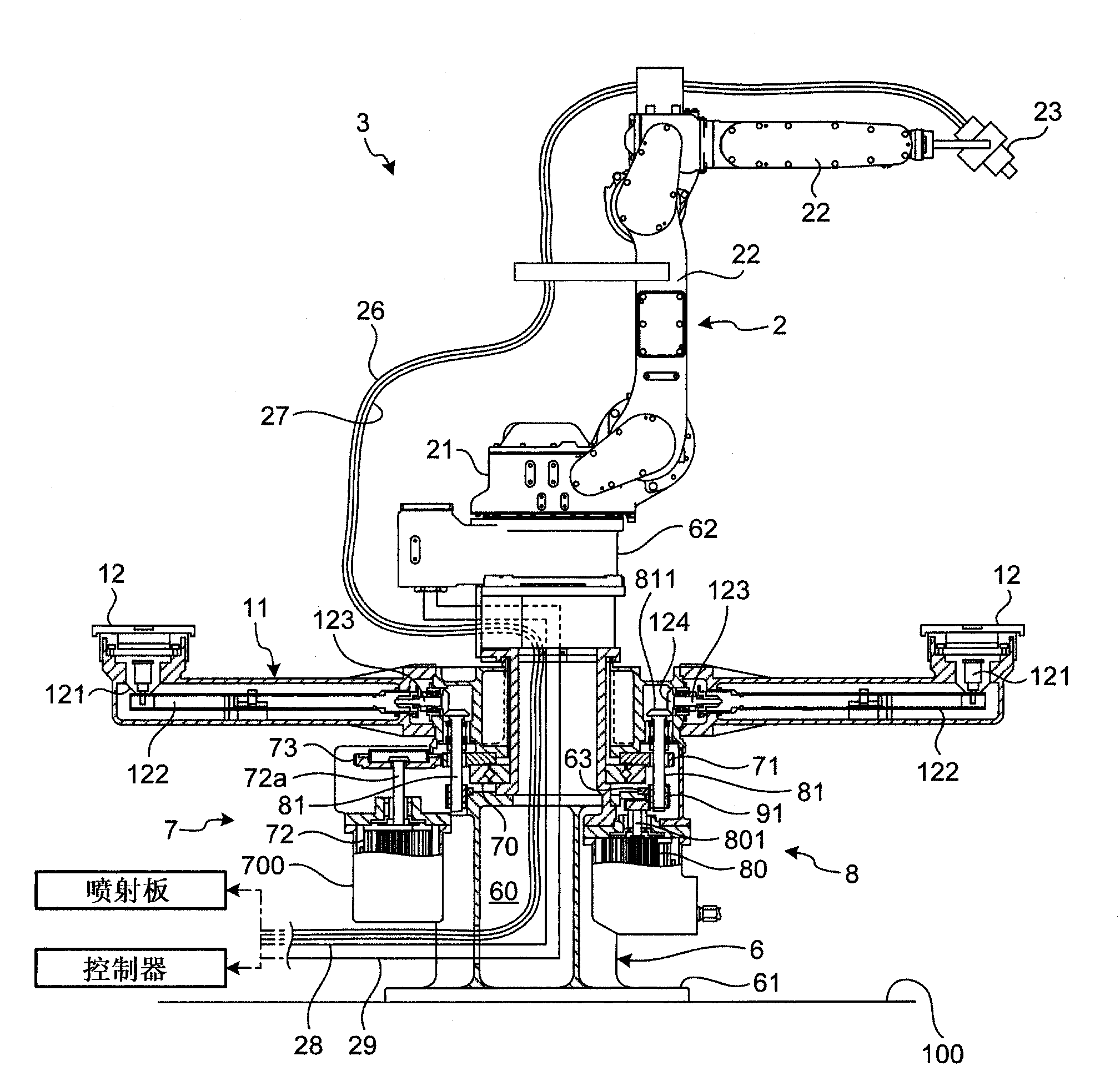
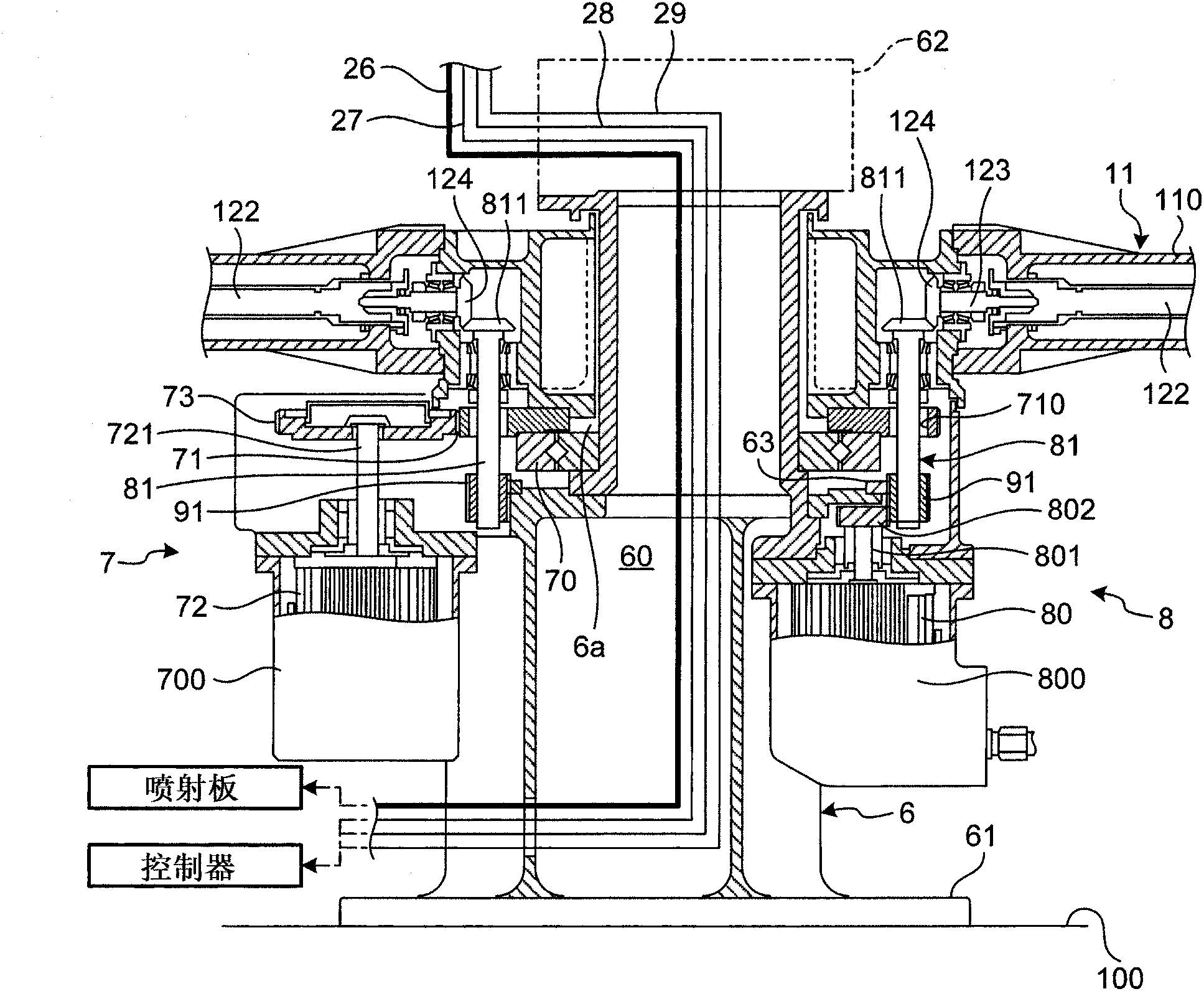
[0019] The conveyance device according to the embodiment includes: a base provided on the installation surface; and a swing arm provided on the base to freely swing, and a turntable attached to both ends of the swing arm is set on a circular track in advance. The transport entry and exit positions and working positions. The abutment has a hollow structure and has a hollow portion having at least a rotation center of the swivel arm therein, and a predetermined linear body is inserted into and passes through the hollow portion.

[0020] Hereinafter, a transfer device and a robot system according to an embodiment of the present disclosure will be described in detail with reference to the accompanying drawings. In addition, the embodiments disclosed below are not intended to limit the present invention.

[0021] robot system

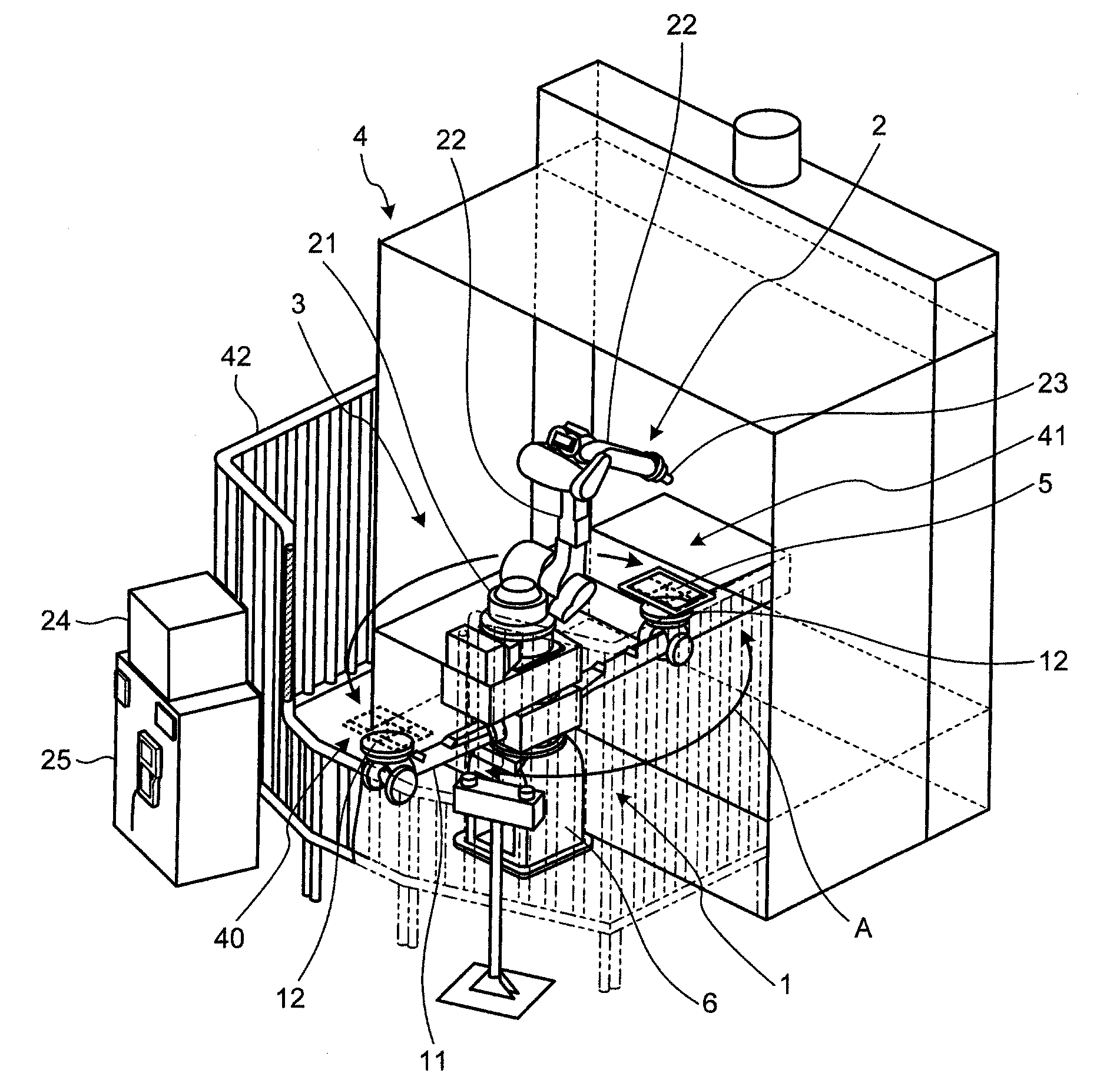
[0022] figure 1 is an explanatory diagram showing a state of use of the robot system 3 according to the embodiment. figure 2 is a partial sectional vie...


PUM


Abstract

A carrier device according to an embodiment includes a base that is disposed on an installation surface and a swivel arm that is provided on the base (6) to swivel freely and of which turn tables (12) attached to its both ends pass between a carrying in and out position and a working position (41) that are previously set on a circular orbit (A). The base (6) has a hollow structure and includes a hollow part (60) that has at least therein the center of rotation of the swivel arm (11) and into and through which a predetermined linear object can be inserted.

Description

technical field [0001] Embodiments discussed herein relate to handling devices and robotic systems. Background technique [0002] A conventional conveying device is known, which is provided on a base to rotate freely, and is provided with a swivel arm, the two ends of which are attached with a turntable on which a workpiece is placed, and the conveying device pre-set on a circular track is known. Pass between the entry and exit position and the working position. [0003] For example, efficient automatic painting work can be performed by combining a transfer device and a painting robot to construct a robot system. [0004] The robot system may be one in which a robot is provided on a carrier to minimize the operating space determined by the range of motion of the swing arm of the carrier, the arm of the robot, etc. (the space required to perform predetermined work by the robot and the carrier). [0005] Conventional techniques have been disclosed in, for example, Japanese P...

Claims


Application Information

Patent Timeline
Patent Type & Authority Applications(China)
IPC IPC(8): B65G47/80B05B13/02
CPCB05B13/0242B05B13/0431B65G47/80B25J9/0096B25J9/04B25J19/00
Inventor 吉野胜彦
Owner YASKAWA DENKI KK
Learn More