
Gas pressure detection system, gas pressure detection plug and gas pressure detection plug assembly

A gas and plug technology, applied in the direction of pipes/pipe joints/fittings, passing components, measuring fluid pressure, etc., can solve problems such as failure to detect buried pipelines, damage to pipelines or equipment, and inability to accurately determine the actual situation of pipelines. The effect of improving work efficiency, inspection accuracy, and safety

Inactive Publication Date: 2013-07-10
伊藤未来能源设备(上海)有限公司
View PDF6 Cites 5 Cited by
  • Summary
  • Abstract
  • Description
  • Claims
  • Application Information

AI Technical Summary

Problems solved by technology

[0003] 1. Although the method of using a leak detector is more intuitive, it cannot accurately determine the actual situation of the pipeline due to the size of the wind force in the inspection environment, whether there is a detection blind spot around it, and the sensitivity of the leak detector. buried pipeline;
[0004] 2. Compared with the leak detector, the smear detection liquid is greatly less affected by the outside world and the equipment itself, but because a large number of pipelines are in a state of concealed laying—that is, buried in the ground or buried in the wall, it is impossible to use smear detection for this part of the pipeline. There is a considerable inspection blind spot;
[0005] 3. For the method of using an external pressure gauge for the existing pipeline, since the pipeline itself does not have a detection port, it is necessary to disassemble a certain part of the pipeline or disassemble the equipment connected to the pipeline, and then connect the pressure gauge to perform inspection operations. Time-consuming and labor-intensive, while dismantling the original pipeline or equipment may easily cause secondary damage

Method used


Image

  • Gas pressure detection system, gas pressure detection plug and gas pressure detection plug assembly
  • Gas pressure detection system, gas pressure detection plug and gas pressure detection plug assembly
  • Gas pressure detection system, gas pressure detection plug and gas pressure detection plug assembly

Examples


Embodiment Construction

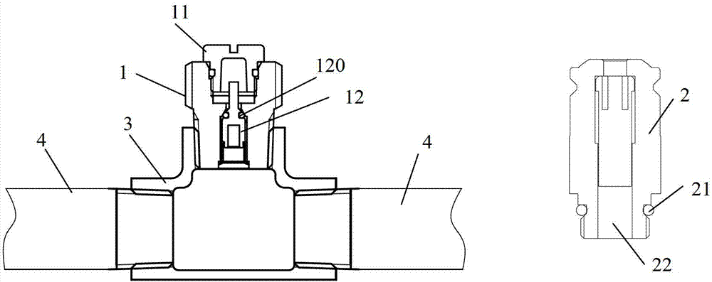
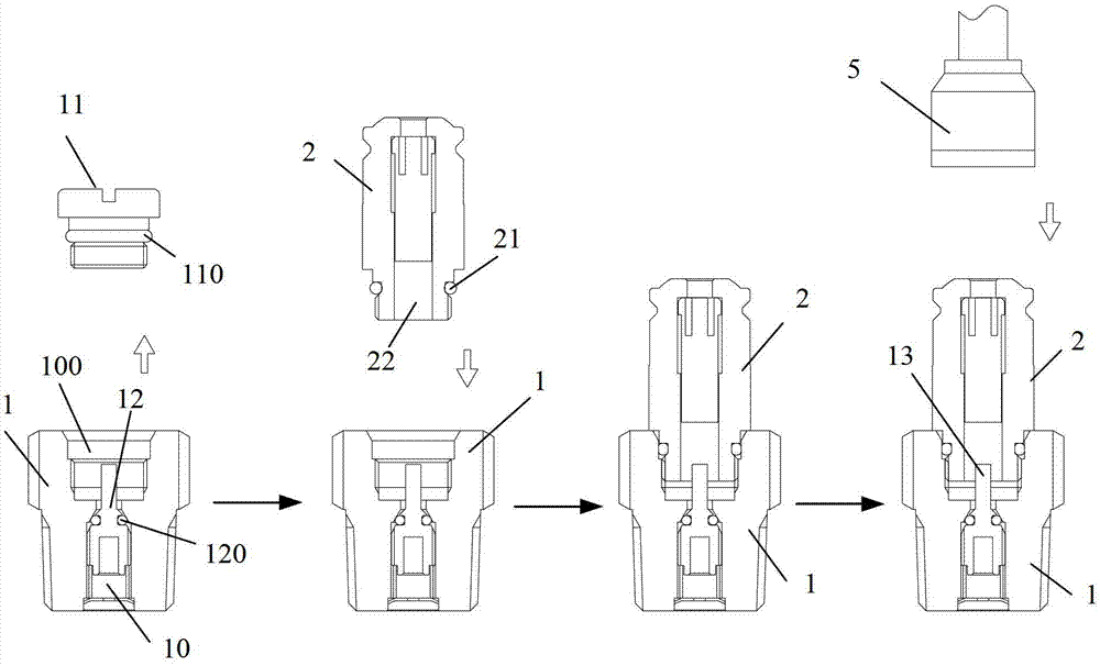
[0025] combine figure 2 and image 3 Embodiments of the gas pressure detection system, the gas pressure detection plug and the gas pressure detection plug assembly of the present invention can be understood.

[0026] exist figure 2 , the seat body of the gas pressure detection plug has been connected to the tee pipe, and the tee pipe is connected in the gas pipeline. Such as figure 2 and image 3 As shown, in the embodiment of the present invention, the gas pressure detection plug assembly includes a seat body 1 suitable for connecting the nozzle of the tee pipe 3 and a quick connector 2, and a gas channel 10 (such as image 3 As shown, up and down through), the middle part of the gas channel 10 is sealed and closed by the check valve 12, and the port 100 of the gas channel 10 of the seat body 1 is also equipped with a head 11. The quick connector 2 has a connecting passage 22, and the lower end of the connecting passage 22 of the quick connector 2 can be tightly conne...


PUM


Abstract

The invention relates to a gas pressure detection system, a gas pressure detection plug and a gas pressure detection plug assembly. By means of the gas pressure detection system, the gas pressure detection plug and the gas pressure detection plug assembly, pressure in a gas pipeline can be conveniently detected, and whether pipeline leakage exists or whether the gas pressure in the pipeline is in a safety range is judged through observation of changing conditions of the pressure. The gas pressure detection system comprises a t-branch pipe, the gas plug and a pressure meter, wherein the t-branch pipe, the gas plug and the pressure meter are arranged in the gas pipeline. The gas plug comprises a seat body and a quick coupler which are connected with an opening of the t-branch pipe. A gas channel is arranged in the seat body and closed by a check valve in a sealed mode, and a sealing head is arranged at a port of the gas channel of the seat body in a matched mode. The quick coupler is provided with a connecting channel. One end of the connecting channel of the quick coupler is connected with the port of the gas channel of the seat body in a sealed mode, wherein the sealing head is screwed out of the port. The connecting channel is used for passing of an ejection rod in a quick insertion head connected with the pressure meter, the ejection rod ejects and opens the check valve to open the gas channel for gas pressure detection, and the check valve can reset elastically.

Description

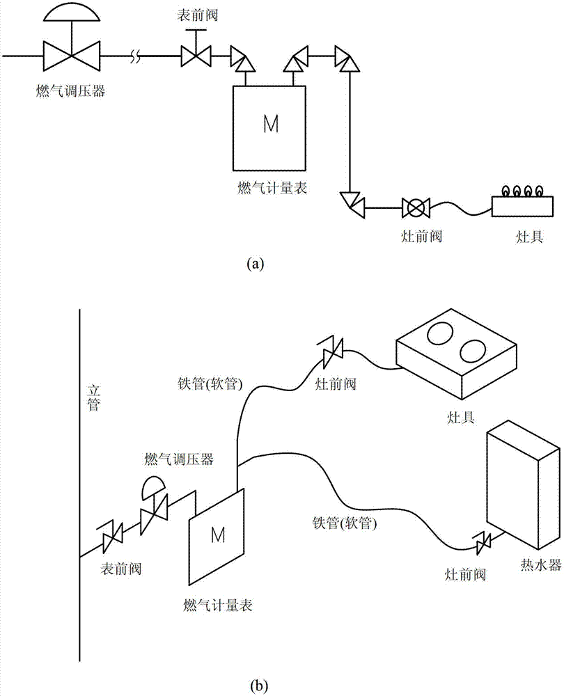
technical field [0001] The invention relates to a pressure detection device for a gas pipeline. Background technique [0002] figure 1 The circuit diagram of the existing gas pipeline laying is shown, which generally does not have a special detection port for detecting the pressure inside the pipeline. But it is impossible to know the actual operation status of the pipeline—that is, whether the pressure in the pipeline meets the actual safety requirements. Therefore, there are certain hidden dangers in the daily operation of the pipeline. In order to avoid unnecessary damage to people and property due to the leakage of gas in the pipeline, leak detectors, smearing detection fluid or pressurizing limited pipelines have been used to detect the pressure drop of the connected pressure gauge for many years. Determine whether there is a hidden danger of pipeline leakage. Its disadvantages mainly include: [0003] 1. Although the method of using a leak detector is more intuit...

Claims


Application Information

Patent Timeline
IPC IPC(8): G01L19/00F16L29/02
Inventor 平山明広
Owner 伊藤未来能源设备(上海)有限公司
Learn More