
Flow-adjustable brew structure

A technology of brewing and flow rate, applied in the field of brewing structure with adjustable flow rate, which can solve the problems of trouble, unsatisfactory structure and usability, time-consuming and so on.

Inactive Publication Date: 2013-07-10
陈人辉
View PDF5 Cites 7 Cited by
  • Summary
  • Abstract
  • Description
  • Claims
  • Application Information

AI Technical Summary

Problems solved by technology

[0005] However, the equipment required for extracting coffee liquid with hot water (such as: siphon pot) or dripping with ice water (such as: ice drip pot) is not the same. If the user wants to change the way of extracting coffee to change the taste of coffee , it is necessary to purchase different equipment, which not only increases the economic load of the user, but also takes up a lot of space, which is not only time-consuming and troublesome, but also very inconvenient for the user.
[0006] To sum up, it can be seen that no matter whether hot water or ice water drip is used to extract coffee liquid, the required equipment (siphon pot, ice drip pot or others) is different, and the user cannot quickly and easily adjust the drip Therefore, the structure and usability of the existing equipment are not ideal. Therefore, how to design an innovative brewing structure so that the user can move the coffee when brewing coffee The position of the tight part in the brewing structure, and then adjust the flow rate and flow rate of the liquid flowing out of the brewing structure, without using other equipment, that can quickly and conveniently brew all kinds of ice and hot coffee, greatly reducing the user's effort Economic load is an important subject that the present invention desires to explore here

Method used


Image

  • Flow-adjustable brew structure
  • Flow-adjustable brew structure
  • Flow-adjustable brew structure

Examples


Embodiment Construction

[0047] In order to further explain the technical solution of the present invention, the present invention will be described in detail below through specific examples.

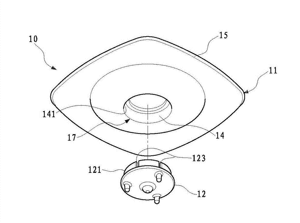
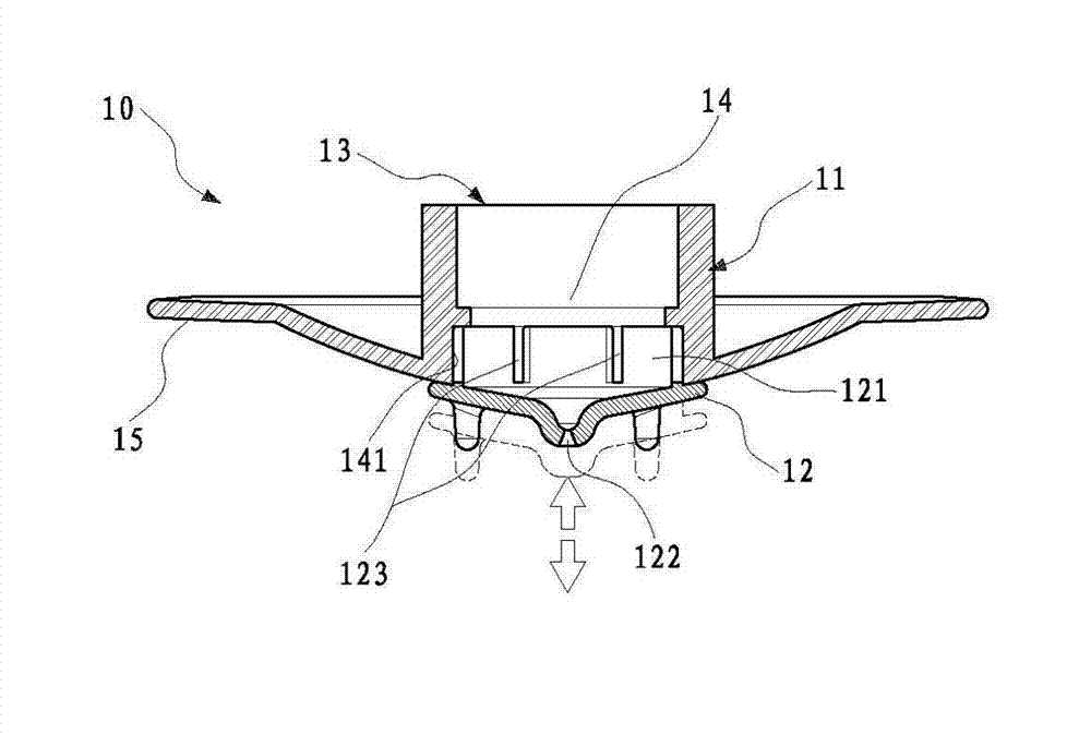
[0048] The present invention is an adjustable flow brewing structure, please refer to the adjustable flow brewing structure 10 shown in Figure 1 and Figure 2, in the first preferred embodiment of the present invention, the adjustable flow brewing The bubble structure 10 includes a body 11 and a valve cover 12, the top surface of the body 11 is provided with a first opening 13, the body 11 is provided with an accommodating space 14, the first opening 13 communicates with the accommodating space 14, For liquid to enter the accommodating space 14 from the first opening 13 .

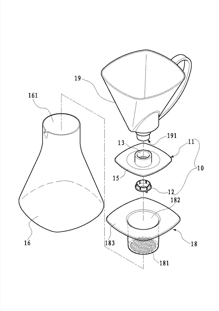
[0049]Please refer to FIG. 3 , a positioning disc 15 is provided on the outer peripheral edge of the main body 11 , and the positioning disc 15 can cover or span a water inlet 161 of a container 16 , so that the main body 11 can be positioned...


PUM


Abstract

The invention discloses a flow-adjustable brew structure, which comprises a body and a valve cover, wherein a first opening, which allows the inflow of liquid and is formed in the top surface of the body, and a second opening, which is formed at the bottom surface thereof, are communicated; a through hole is formed on the valve cover, and a tightening part is arranged at the periphery of the top surface of the valve cover in a circling manner; a plurality of groove ports are formed on the tightening part in a penetrating manner; the tightening part can enter and be accommodated in the body through the second opening so as to be tightly propped against and positioned on the inner side wall of the body, and the groove ports can be closed by the inner side wall of the body; under the condition that part of the tightening part is moved to be exposed out of the accommodating space, some of the groove ports are accordingly moved to be exposed out of the accommodating space, so that the liquid in the body can flow out through not only the through hole but also the groove ports, and accordingly, the liquid flow speed and flow can be quickly adjusted as long as a user adjusts the position of the tightening part on the body, so as to easily and conveniently brew various iced drinks and hot beverages.

Description

technical field [0001] The invention relates to a brewing structure, in particular to a brewing structure with adjustable flow. Background technique [0002] In recent years, with the rapid development of the economy, the life of modern people has become more and more affluent, so they have begun to pay attention to the taste of life; as the population of Chinese people who like to drink coffee is increasing, many people regard coffee culture as the taste of life. One of the signs. [0003] Generally, when brewing coffee, most users first grind the roasted coffee beans into powder, then place them in the brewing pot, and use hot water with steam or pressure to extract the hot coffee liquid. If you want to drink ice , you need to put ice cubes into the hot coffee liquid to cool down the hot coffee liquid to obtain iced coffee, but this will easily cause the acidification and dilution of the coffee. Although it can cool the coffee, it will destroy its original mellow taste; ...

Claims


Application Information

Patent Timeline
Patent Type & Authority Applications(China)
IPC IPC(8): A47J31/00A47J31/46
CPCA47J31/0621A47J31/46
Inventor 陈人辉
Owner 陈人辉
Learn More