Stirring shaft of hard ice cream machine

A hard ice cream and stirring shaft technology, applied in the field of stirring shafts, can solve the problems of increasing motor load, increasing motor heat, and not being able to clean the frozen material layer better, achieving good lubrication and wear resistance, sharp cutting edges, and reduced The effect of small load

Inactive Publication Date: 2013-07-10
OCEANPOWER FOOD TECH +2
View PDF3 Cites 14 Cited by
  • Summary
  • Abstract
  • Description
  • Claims
  • Application Information

AI Technical Summary

Problems solved by technology

[0002] The refrigeration device of the hard ice cream machine covers the outer surface of the freezing cylinder. On the inner wall of the freezing cylinder, a layer of frozen material will be formed due to the low temperature. Since the freezing cylinder and the stirring shaft are of fixed size, there will be a gap between the inner wall of the freezing cylinder and the stirring shaft. There is a certain gap, so that the ice cream slurry condenses on the inner wall of the freezing cylinder, resulting in a decrease in the heat transfer rate inside and outside the freezing cylinder. During the operation of the stirring shaft, the frozen material layer attached to the inner wall of the freezing cylinder cannot be better cleaned. Blocks of frozen slurry are easily mixed into the slurry, which affects the taste of ice cream. At the same time, the resistance generated when the stirring blade scrapes the frozen material layer is transmitted to the motor through the pulley and belt, which increases the load on the motor and increases the heat of the motor. , affecting the service life of the motor

Method used


Image

  • Stirring shaft of hard ice cream machine
  • Stirring shaft of hard ice cream machine
  • Stirring shaft of hard ice cream machine

Examples


Embodiment Construction

[0024] The present invention will be further described below in conjunction with the accompanying drawings and embodiments.

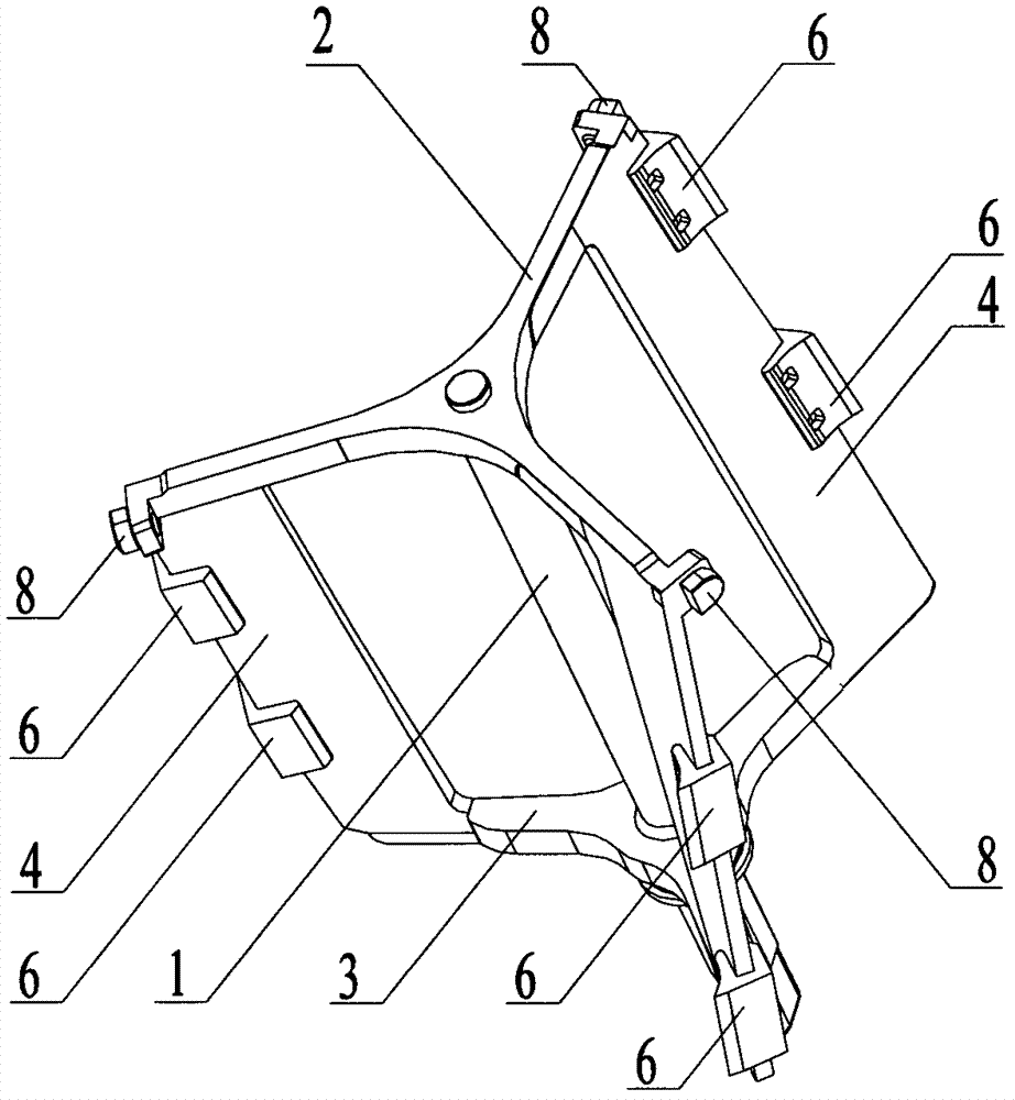
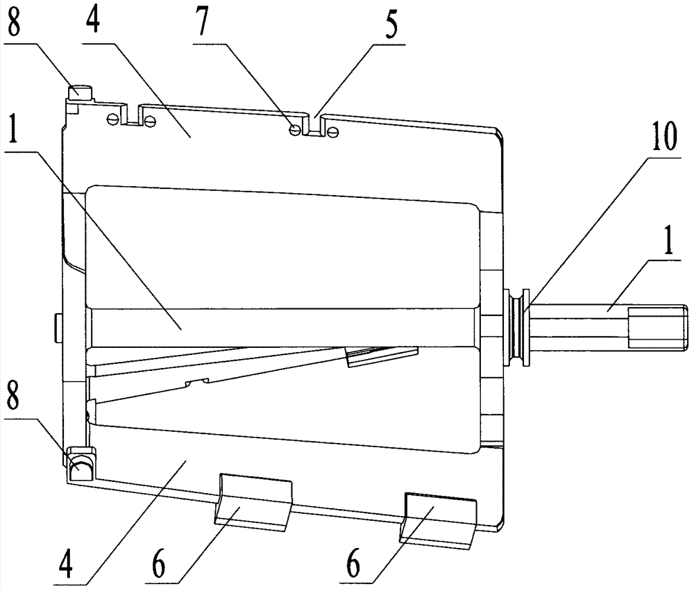
[0025] In this example, figure 1 , figure 2 Shown is the main structure of the stirring shaft. The first bracket 2 and the second bracket 3 are installed on the central shaft 1. The first bracket 2 and the second bracket 3 rotate around the central shaft 1 at an angle of 15°. Each bracket contains three Forks, every two forks are at an angle of 120°, and the stirring blade 4 is installed between the two brackets. During the operation of the stirring shaft of this structure, the ice cream slurry can have a flow tendency, which is beneficial to the discharge from the material. Mouth discharge. But in other embodiments, the central main shaft 10 and the stirring blade 4 can be connected by any known bracket structure, and the stirring blade 4 can be set to two or more pieces according to the number of bifurcations of the bracket, and the two brackets ca...


PUM


Abstract

The invention discloses a stirring shaft of a hard ice cream machine. The stirring shaft comprises a central spindle, stirring blades and a bracket connecting the central spindle and the stirring blades. An outer edge of each stirring blade is provided with at least a positioning groove for installing wiper blades; a wiper blade comprises a cutting edge and is capable of sliding in a preset length along a radial direction of the stirring shaft. Because the wiper blades have a cutting edge structure, when the stirring shaft operates, cutting action on a freezing material layer on an inner wall of a congelation tank is enhanced, thereby improving the heat transfer speed inside and outside the congelation tank, and reducing load of a motor.

Description

technical field [0001] The invention relates to a stirring shaft of a hard ice cream machine. Background technique [0002] The refrigeration device of the hard ice cream machine covers the outer surface of the freezing cylinder. On the inner wall of the freezing cylinder, a layer of frozen material will be formed due to the low temperature. Since the freezing cylinder and the stirring shaft are of fixed size, there will be a gap between the inner wall of the freezing cylinder and the stirring shaft. There is a certain gap, so that the ice cream slurry condenses on the inner wall of the freezing cylinder, resulting in a decrease in the heat transfer rate inside and outside the freezing cylinder. During the operation of the stirring shaft, the frozen material layer attached to the inner wall of the freezing cylinder cannot be better cleaned. Blocks of frozen slurry are easily mixed into the slurry, which affects the taste of ice cream. At the same time, the resistance generat...

Claims


Application Information

Patent Timeline
IPC IPC(8): A23G9/12
Inventor 彭仙明何唯平
Owner OCEANPOWER FOOD TECH
Why Eureka
Try Eureka